
Short description
MultiOffsetBothSidesWithLayerExtra / MOBSWLE is an AutoCAD and Autodesk Civil 3D C# .NET plugin for creating multiple parallel offsets on both sides of selected line or polyline geometry. It is designed for utility, pipe, duct, Schutzrohr, KK, and DN layout workflows where users need fast, repeatable, layer-controlled offset generation with live WinForms preview, model-space transient preview, Apply, Undo last, profile management, and run logging.
Command:
The plugin is loaded in AutoCAD or Civil 3D with
NETLOAD by selecting MOBSWLE.dll. The main commands are MOBSWLE and MultiOffsetBothSidesWithLayerExtra, both opening the same modeless WinForms tool window.
Additional utility commands include OLPredefinedProfiles for managing predefined offset profiles and OLDebug for printing the current in-memory log to the AutoCAD command line.
The target platform is x64 AutoCAD / Civil 3D using .NET Framework 4.8, System.Windows.Forms, and AutoCAD managed API objects such as Document, Editor, Database, Transaction, Curve.GetOffsetCurves(), LayerTableRecord, and TransientManager.
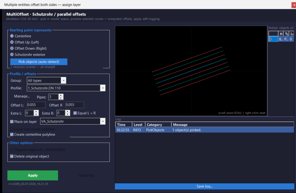
The main workflow is simple: run MOBSWLE, pick model-space objects, choose a profile and offset options, review the WinForms and model-space preview, press Apply, and use Undo last when the last generated batch needs to be removed.
Description:
This project is a C# .NET plugin port and extension of an AutoLISP-style multi-offset workflow. Its main purpose is to automate the creation of parallel pipe, duct, casing, Schutzrohr, KK, and DN geometry in AutoCAD and Civil 3D drawings.
The user selects existing centerline or reference geometry, chooses a predefined profile such as
1_Schutzrohr.DN 110, Schutzrohr.DN 160, KK profiles, or DN profiles, then defines the number of pipes, left and right offsets, extra ducts, start mode, target layer behavior, centerline generation, closing behavior, and original-object handling.
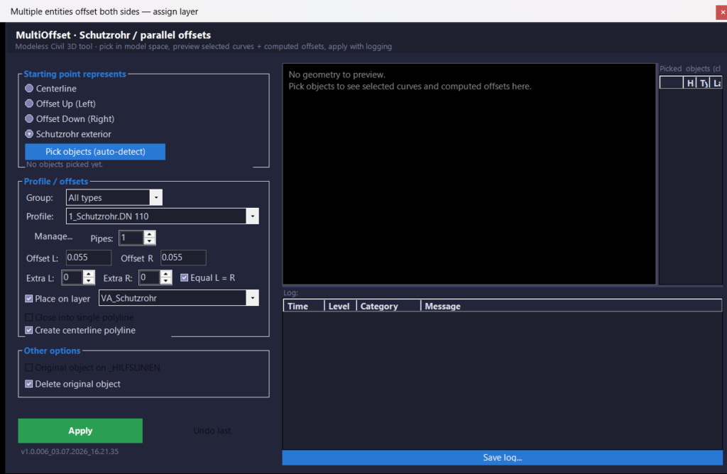
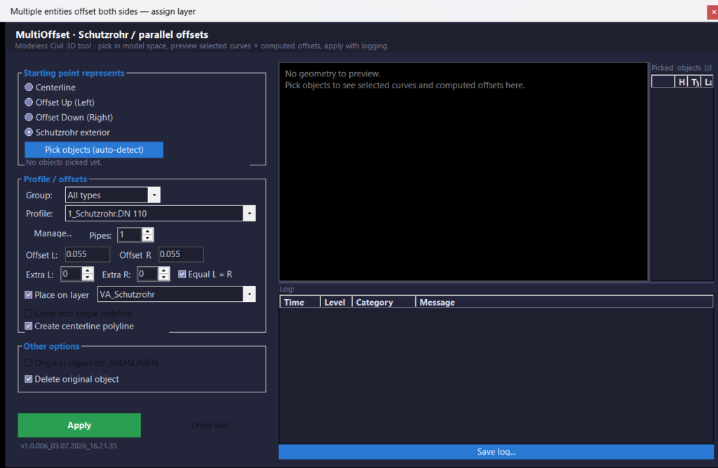
The plugin uses a modeless WinForms interface so the user can keep the tool open while interacting with Civil 3D model space. When objects are picked, the form temporarily hides during AutoCAD selection and then restores itself, avoiding common modeless-form selection conflicts. Picked objects appear in a grid, and selecting a row highlights the matching AutoCAD entity using Editor.SetImpliedSelection().
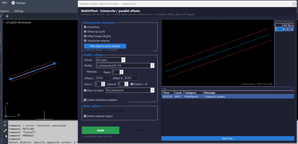
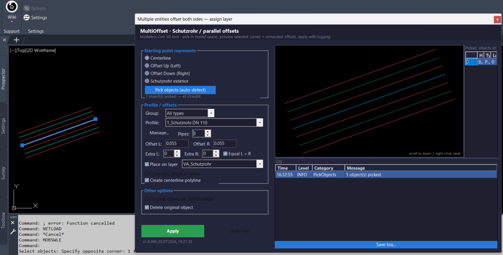
The tool also includes a dark Civil 3D-style UI theme, a zoomable 2D preview panel, live model-space transient graphics, a scroll-friendly settings panel, and fixed bottom action buttons for Apply and Undo last.
Internally, the plugin computes offset distances through OffsetPlan, then uses the same offset plan for both preview and final geometry creation. This reduces the risk that the preview differs from the entities written to the DWG.
The final drawing objects are created through OffsetEngine.RunSelectCenterlines(), which opens a transaction, creates required layers, generates offset curves from selected AutoCAD Curve entities, optionally creates helper centerlines on _HILFSLINIEN, applies target layer settings, and records created and modified object IDs for the custom undo workflow.
For Civil 3D SEO context, this tool is useful in plan production and utility design environments where designers work with alignments, corridor-related base geometry, pipe routes, duct banks, cable protection pipes, and construction plan drawings.
It does not currently automate Civil 3D-specific ProfileView, SectionView, Alignment label, band set, style assignment, or export workflows. Instead, it focuses on high-speed AutoCAD geometry generation inside Civil 3D drawings, especially where accurate offset spacing, layer naming, linetypes, and repeatable profile standards are important.
Helper function: (if any)
- 🧠 Shared offset calculation with
OffsetPlan— centralizes pipe count, left/right offset, extra duct, Schutzrohr, and start-shift logic so the WinForms preview, model-space transient preview, and final Apply operation use the same geometry plan. - 📐 Offset creation with
OffsetEngine.RunSelectCenterlines()— processes picked AutoCADCurveobjects, callsCurve.GetOffsetCurves(), writes new entities to the current space, and applies the selected layer configuration in one controlled transaction. - 🎨 Layer automation with
LayerManager.EnsureLayer()— creates missing target layers such asVA_Schutzrohrand_HILFSLINIEN, applies color, linetype, and lineweight, and attempts to load missing linetypes fromacadiso.linoracad.lin. - 🔍 Live model-space preview with
ModelSpacePreviewController— uses AutoCADTransientManagerto display temporary offset geometry directly in model space without writing preview objects into the DWG database. - 🟧 Zoomable WinForms preview with
PreviewControl— shows selected curves, computed offsets, and helper centerlines in a dark preview canvas, with mouse-wheel zoom and right-click reset for quick visual checking. - 🔄 Debounced preview refresh with
WinFormsDebouncer— reduces UI lag by delaying preview rebuilds while the user is typing offset values or changing numeric options. - 🔒 Safe modeless selection with
AcadDocumentService.GetSelectionWithHiddenOwner()— hides the WinForms dialog during AutoCAD object selection and restores it afterward, including cancel or Escape workflows. - 📝 Session logging with
LoggerandLogPanel— records time, level, category, and message for picking, layer creation, offset processing, Apply, Undo, warnings, and errors, with optional saved log output. - 📊 Profile persistence with
ProfileStore— stores predefined profiles and group checkbox behavior in XML under%APPDATA%\MultiOffsetBothSidesWithLayerExtra, keeping user settings separate from the compiled DLL. - 🔢 Input validation with
InputValidator.TryParsePositiveDistance()— validatesOffset LandOffset Ras positive numeric distances and supports invariant and current-culture parsing. - 📌 Picked-object management with
PickedObjectsPanel— displays selected entity handles, object types, and layers so the user can verify which AutoCAD entities will be processed before applying offsets. - 🧹 Undo tracking with
OffsetRunResult— records created entities, original layers, and erased source objects soUndo lastcan remove the last applied offset batch and restore modified source geometry.
Functionalities:
- 🚀 Multiple offsets on both sides — generates parallel geometry to the left and right of picked centerlines or reference curves, reducing repetitive manual
OFFSETcommands. - 📐 Profile-based pipe and duct spacing — uses predefined Schutzrohr, KK, and DN profiles with stored offsets, pipe counts, layer names, color indexes, linetypes, and lineweights for consistent Civil 3D drawing standards.
- 🟢 Apply workflow — commits previewed geometry into the DWG only when the user presses
Apply, making the process clearer than immediate one-step execution. - 🔴 Undo last workflow — removes the last generated batch, restores original object layers, and unerases source objects when
Delete original objectwas enabled. - 🔍 Live model-space preview — displays temporary offset geometry inside AutoCAD / Civil 3D model space while changing WinForms variables such as pipe count, offsets, extra ducts, and start mode.
- 🎨 Civil 3D-style dark UI — provides a compact, themed WinForms interface with grouped settings, preview panel, picked-object grid, and log viewer for a more production-friendly CAD workflow.
- 🔄 Start mode control — supports
Centerline,Offset Up (Left),Offset Down (Right), andSchutzrohr exteriorso the selected object can represent different reference positions. - 🧩 Schutzrohr helper logic — detects Schutzrohr profile groups, supports DN 110 and DN 160 diameter logic, and can create helper pipe centerlines on
_HILFSLINIEN. - 🏷️ Automatic layer creation — creates target layers when missing and applies profile-defined color, linetype, and lineweight, improving layer discipline in AutoCAD and Civil 3D production drawings.
- 🧹 Original object handling — can keep originals, move originals to
_HILFSLINIEN, move originals to the target layer, or delete originals after generating the final offset geometry. - 📊 Run log and diagnostics — records pick counts, selected profile, pipe count, start mode, layer creation, processing messages, warnings, Apply results, and Undo results for quality control and troubleshooting.
- 📘 Profile management dialog — allows editing of profile data and group defaults through
OLPredefinedProfilesor the Manage button in the main UI. - 🔐 Short project naming for build reliability — uses the short physical project name
MOBSWLEand output assemblyMOBSWLE.dllto reduce Windows path-length problems in long OneDrive or Civil 3D support-folder paths. - 🧰 Plain AutoCAD entity focus — works with standard AutoCAD geometry such as
Line,Polyline,Polyline2d, and generalCurveobjects inside Civil 3D drawings.
Result:
The final result is a productivity-focused AutoCAD / Civil 3D offset automation tool that turns selected centerlines or reference curves into organized, layer-controlled parallel pipe and duct geometry.
Instead of manually offsetting each side, changing layers, creating helper lines, checking pipe spacing, and cleaning up originals by hand, the user can select a profile, preview the result, apply the geometry, and undo the last operation when needed.
This improves drawing speed, reduces repetitive drafting steps, supports better CAD quality control, and helps maintain consistent Civil 3D drawing management for utility, Schutzrohr, KK, DN, and duct-bank plan production.
Important code notes: the current implementation focuses on the select-centerlines workflow.
RunTwoPoints() and RunChangeExisting() are present but intentionally throw NotImplementedException.
The project uses AutoCAD managed APIs and does not currently implement Civil 3D-specific automation for ProfileView, SectionView, Alignment objects, labels, bands, styles, or export.
Offset direction can depend on the source curve direction and AutoCAD offset behavior, so left/right results should be tested with local drawing standards.
The build expects AutoCAD / Civil 3D managed references from the configured AutoCAD_Civil3D_refferences.props file and should be built as x64 for modern AutoCAD / Civil 3D versions.
Images, animations etc.
XAML code:
<ResourceDictionary
xmlns="http://schemas.microsoft.com/winfx/2006/xaml/presentation"
xmlns:x="http://schemas.microsoft.com/winfx/2006/xaml"
xmlns:src="clr-namespace:Autodesk.Windows;assembly=AdWindows">

<src:RibbonToolTip x:Key="MultiOffsetBothSidesWithLayer">
<src:RibbonToolTip.ExpandedContent>
<StackPanel>
<TextBlock Background="AntiqueWhite" TextAlignment="Left">
<Bold>Function Syntax: MultiOffsetBothSidesWithLayerExtra / MOBSWLE / OLPredefinedProfiles / OLDebug</Bold>
<LineBreak/>
<Bold>Version: 1 Date: 07.11.2025</Bold>
<LineBreak/>
<Bold>Version: 2 Date: 23.06.2026 7:15:55PM</Bold>
<LineBreak/>
<Bold>Version: 3 Date: 03.07.2026 4:21:35PM</Bold>
<LineBreak/>
<Hyperlink>AI</Hyperlink>
<LineBreak/>
<Bold>Description</Bold><LineBreak/>
This AutoLISP program allows the user to <Span Foreground="DarkRed">offset multiple lines on both sides simultaneously</Span> with customizable distances, profiles, and target layers.
It includes interactive dialogs for configuration and layer selection, enhancing workflow efficiency when creating symmetrical line offsets in AutoCAD drawings.<LineBreak/>
<Bold>Main Function:</Bold><LineBreak/>
• Command name: <Span Foreground="Red">c:MultiOffsetBothSidesWithLayer</Span><LineBreak/>
• The user is prompted to select one or more <Span Foreground="DarkRed">LINE</Span> objects.<LineBreak/>
• The program displays a custom <Span Foreground="DarkRed">dialog box</Span> for offset settings.<LineBreak/>
• It then performs <Span Foreground="DarkRed">offsets on both sides</Span> of each selected line using specified distances and optionally places results on a chosen layer.<LineBreak/>
<Bold>Program Flow</Bold><LineBreak/>
• <Span Foreground="Red">Step 1:</Span> User selects lines to offset using <Span Foreground="DarkRed">(ssget ":L" '((0 . "*LINE")))</Span> — multiple passes allowed until Enter is pressed.<LineBreak/>
• <Span Foreground="Red">Step 2:</Span> The program opens a dialog for offset configuration — controlled by <Span Foreground="DarkRed">OL-ShowMainDialog</Span>.<LineBreak/>
• <Span Foreground="Red">Step 3:</Span> User can choose a predefined <Span Foreground="DarkRed">profile</Span> (e.g., "Schutzrohr.DN 110", "KK Gr. II i.F_400X275") to automatically set left and right offset distances.<LineBreak/>
• <Span Foreground="Red">Step 4:</Span> Option to <Span Foreground="DarkRed">delete the original line</Span> after offsetting.<LineBreak/>
• <Span Foreground="Red">Step 5:</Span> Option to <Span Foreground="DarkRed">assign new offsets to a specific layer</Span> via <Span Foreground="DarkRed">OL-ChooseLayer</Span> dialog, which filters and lists non-XREF layers.<LineBreak/>
• <Span Foreground="Red">Step 6:</Span> Executes offset operation using AutoCAD command <Span Foreground="DarkRed">_.offset</Span> in “Source” mode.<LineBreak/>
• <Span Foreground="Red">Step 7:</Span> For each selected line:<LineBreak/>
  – If a target layer is set, it changes the line’s <Span Foreground="DarkRed">DXF layer (group 8)</Span>.<LineBreak/>
  – Performs <Span Foreground="DarkRed">right</Span> and <Span Foreground="DarkRed">left</Span> offsets with the chosen distances.<LineBreak/>
  – Optionally deletes the original entity using <Span Foreground="DarkRed">(vla-erase)</Span>.<LineBreak/>
<Bold>Global Variables Initialized</Bold><LineBreak/>
• <Span Foreground="DarkRed">ol-profiles</Span> — predefined offset profiles with left/right distances.<LineBreak/>
• <Span Foreground="DarkRed">ol-offL</Span>, <Span Foreground="DarkRed">ol-offR</Span> — default offset distances (left/right).<LineBreak/>
• <Span Foreground="DarkRed">ol-delorig</Span> — whether to delete the original line (1 = yes).<LineBreak/>
• <Span Foreground="DarkRed">ol-use-layer</Span> — whether to place offset lines on a chosen layer.<LineBreak/>
• <Span Foreground="DarkRed">ol-layer</Span> — stores chosen layer name.<LineBreak/>
<Bold>Dialog System Features</Bold><LineBreak/>
• Offset distances editable manually.<LineBreak/>
• Dynamic profile selection updates offsets automatically using <Span Foreground="DarkRed">OL-Profile-Change</Span>.<LineBreak/>
• Checkbox toggles for “Delete Original” and “Place on Layer.”<LineBreak/>
• Layer filter system allows partial name search and layer selection via <Span Foreground="DarkRed">DCL</Span> interface.<LineBreak/>
• Option to <Span Foreground="DarkRed">pick a layer from an existing object</Span> directly from the drawing.<LineBreak/>
<Bold>Key Functions</Bold><LineBreak/>
• <Span Foreground="DarkRed">OL-CollectLines</Span> — gathers all selected line entities.<LineBreak/>
• <Span Foreground="DarkRed">OL-GetAllLayers</Span> — retrieves non-XREF layer names.<LineBreak/>
• <Span Foreground="DarkRed">OL-ChooseLayer</Span> — opens dialog for filtering and choosing layers.<LineBreak/>
• <Span Foreground="DarkRed">OL-Profile-Change</Span> — updates offset distances based on selected profile.<LineBreak/>
• <Span Foreground="DarkRed">OL-ShowMainDialog</Span> — main interface for user input.<LineBreak/>
<Bold>Special Notes</Bold><LineBreak/>
• Uses AutoLISP and(vl-load-com) for full ActiveX and DCL dialog support.<LineBreak/>
• Offsets are performed through <Span Foreground="DarkRed">(vla-offset)</Span> ensuring proper layer inheritance.<LineBreak/>
• Original entity removal is handled through <Span Foreground="DarkRed">(vla-erase)</Span>.<LineBreak/>
• Temporary DCL files are created dynamically using <Span Foreground="DarkRed">(vl-filename-mktemp)</Span> and deleted after use.<LineBreak/>
<Bold>Result</Bold><LineBreak/>
The final outcome is a set of new offset lines created on both sides of the originals, with customizable spacing and layering — ideal for ducting, piping, or structural linework drafting workflows in AutoCAD.<LineBreak/>

</TextBlock>

<Grid>
<Image Source="Image_000.png" Stretch="Uniform"/>
</Grid>

<Grid>
<Image Source="Image_001.png" Stretch="Uniform"/>
</Grid>

<Grid>
<Image Source="Image_002.png" Stretch="Uniform"/>
</Grid>

<Grid>
<Image Source="Image_003.png" Stretch="Uniform"/>
</Grid>

<Grid>
<MediaElement
 Source="Animation_000.gif"
 Stretch="Uniform"
 Visibility="Visible"/>
 </Grid>

</StackPanel>
</src:RibbonToolTip.ExpandedContent>
</src:RibbonToolTip>
</ResourceDictionary>
Additional info:
Based on / Source code:
Open Website
Leave a Reply
You must be logged in to post a comment.