
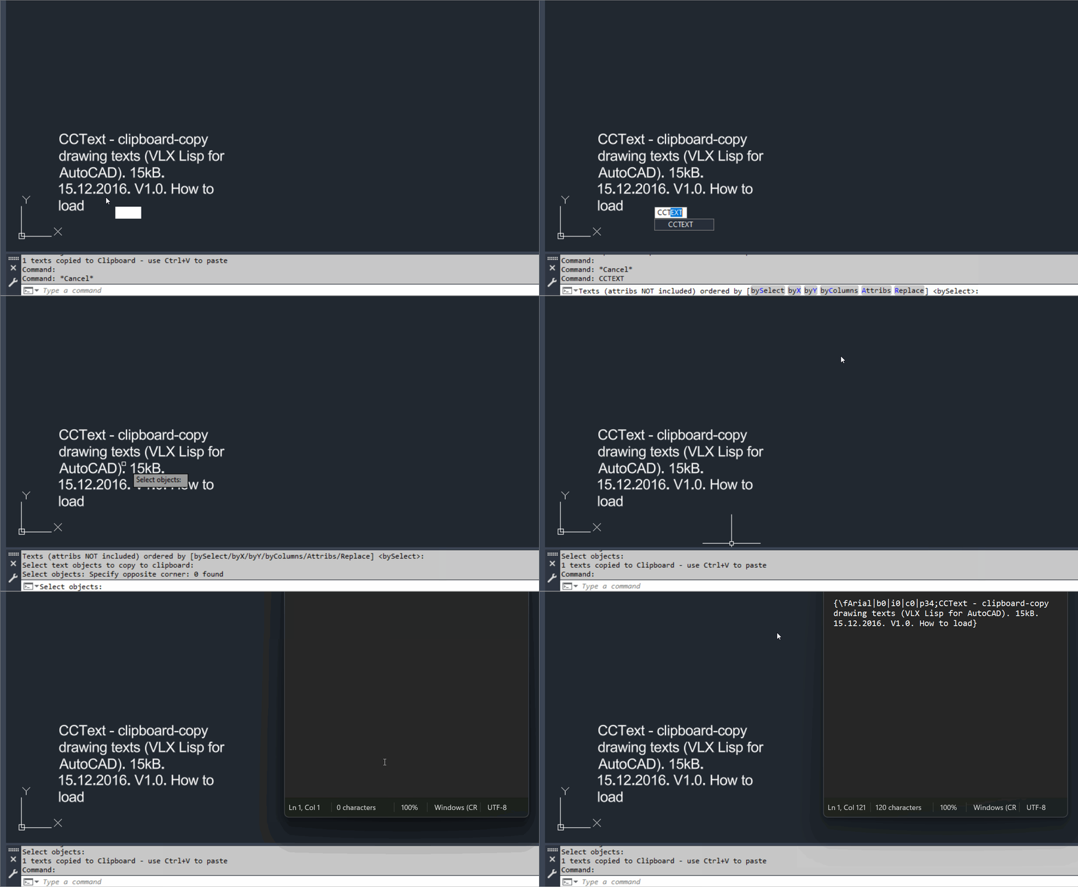
CopyClipboardText
📦 The CADforum download identifies CCText as a compiled VLX LISP application for AutoCAD.
📝 The utility mass copies selected drawing texts from the current AutoCAD drawing to the Windows Clipboard.
🔤 Supported documented content includes single line text paragraph text and optionally block attributes.
🎛️ The Attribs option controls whether attributes are accepted into the clipboard export.
🖱️ Default output order follows the order in which text objects are selected.
↔️ X ordering sorts selected text left to right.
↕️ Y ordering sorts selected text top down.
📊 Column ordering sorts top down and then left to right by columns.
🔎 The tool can preset automatic replacement of a selected substring in transferred text.
↵ MTEXT paragraph control codes are normally reformatted so the paragraph separator becomes a new line.
⚙️ Setting _CCtextNoReformat to T disables the automatic paragraph control code replacement.
🌐 Source reference: https://www.cadforum.cz/en/download.asp?file=CCText
🌐 Functional description reference: https://www.cadforum.cz/en/copy-multiple-dwg-drawing-texts-to-the-windows-clipboard-tip11223Spline2Poly
🎛️ The DCL is written to a unique temporary file on each run.
🖱️ Manual mode asks the user to select SPLINE entities.
🌐 All mode gathers all SPLINE entities in the complete drawing.
🔒 Splines on locked or frozen layers are skipped.
🗂️ The routine switches to the entity layout or model tab when required before calling SPLINEDIT.
⚙️ SPLINEDIT converts the source using polyline precision 1.
📊 The command tracks Converted Skipped and Failed totals.
↩️ Processing is wrapped in an AutoCAD undo group and the original CTAB and CMDECHO values are restored.Slope_Ro
📍 The user picks a starting point followed by an ending point.
🧮 The absolute XY slope is calculated from the coordinate differences.
📏 The source uses slope_v equal to 12 as a fixed imperial style reference.
➗ The integer horizontal component and 12 reference are simplified with a greatest common divisor loop.
📐 The slope angle is calculated with atan and converted to degrees.
📢 An alert displays Slope_Ro ratio and Angle.
↩️ The source starts an AutoCAD undo group although the current implementation does not create annotation geometry.SelectStraightEntities
🌐 The routine scans the current CTAB only using global selection filters.
📏 LINE objects are accepted when their XY direction is orthogonal within a small tolerance.
📐 LWPOLYLINE and POLYLINE objects are accepted only when every checked segment is orthogonal.
⭕ Any nonzero bulge value causes the polyline to be rejected.
🚫 Objects on PAGE_LIMIT_02 are skipped regardless of geometry.
✅ All accepted entities are combined and made the active AutoCAD selection set.ParallelPolylinesOption
🔗 Close mode accepts LWPOLYLINE LINE ARC and SPLINE entities and converts supported selections to lightweight polylines for processing.
2️⃣ Exactly two resulting polylines are required for the close workflow.
➗ When enabled the centerline is created while the two side polylines are still separate.
📏 The routine evaluates the two possible endpoint pairings and chooses the pairing with the shorter total connector distance.
➕ Two connector LINE entities are created and PEDIT Multiple Join combines the pair into one polyline.
✂️ Unclose mode accepts closed LWPOLYLINE objects and identifies the two shortest closed segments as end connectors.
↔️ The remaining vertex paths are rebuilt as two separate open lightweight polylines.
🧬 Layer color linetype and lineweight are preserved for the rebuilt unclosed sides.
🎛️ Apply and Undo use AutoCAD UNDO marks and Cancel rolls back Apply operations from the dialog session.PLTools
➕ PL-VFI inserts vertices at intersections with specified geometry.
🧭 PL-CW and PL-CCW normalize polyline direction clockwise or counterclockwise.
🔄 ENTREV and ENTREVS reverse complete objects or selected object portions.
↔️ PL-L2A and PL-A2L convert line segments to arc segments and arc segments to line segments.
🔗 PL-JOIN and PL-JOIN3D provide joining workflows for 2D and 3D polyline geometry.
✂️ PL-DIV and PL-DIVALL divide selected or all polyline segments.
📍 PL-VxAdd Pl-VxRdc Pl-VxDel PL-VxOpt PL-VxMove and PL-Vx1 provide multiple vertex editing and optimization workflows.
📐 PL-SgInfo reports segment information and PL-SgWidth changes segment start and end width.
🧬 ConvTo2d and ConvTo3d convert between 2D and 3D polyline representations.
🧲 PL-CSE performs chain selection using connected entity relationships.
🎯 MPL creates a middle polyline style result and PL-P90 contains a 90 degree polyline construction workflow.
🎛️ PL-MENU and PLTOOLS-MENU expose the combined command set through a menu interface.OffsetAndLayer
📏 The default offset distance is 0.20 when no saved value exists.
🗂️ The layer list excludes Xref dependent layers containing the vertical bar separator.
🔎 The Filter Layers field performs case insensitive substring matching over the available layer names.
↔️ The direction can be selected as Inward or Outward and Inward is the default when no saved direction exists.
🖱️ After dialog acceptance the user selects POLYLINE ARC CIRCLE ELLIPSE or SPLINE style objects.
📐 The routine excludes AcDb3dPolyline and requires vlax curve planarity.
🧮 A first positive offset is created and its Area is compared with the source Area to determine whether the direction matches Inward or Outward.
🔄 When the first sign gives the wrong area relationship the offset is deleted and the opposite sign is tried.
🗂️ Successful new offset geometry is assigned to the selected target layer.MultiOffsetBothSidesWithLayer
📚 The profile store contains Profile_000 Profile_003 Profile_000 Profile_003 cable channel Profile_002 and Profile_003 bundle profile groups.
🔢 Pipe Count controls the planned repeated pipe or duct boundary offsets.
↔️ Offset L and Offset R provide independent left and right distances.
➕ Extra L and Extra R add additional parallel offsets outside the main planned boundaries.
📍 Starting point represents supports Centerline Offset Up Left Offset Down Right and Profile_000 Exterior modes in the settings model.
🗂️ Place on layer assigns generated geometry to a selected target layer and LayerManager can create the layer using profile color linetype and lineweight.
🔗 Close into single polyline connects and joins the left and right result pair when applicable.
➗ Create centerline polyline builds a midpoint centerline on _HILFSLINIEN.
🧯 Profile_000 profiles can generate pipe centerline helper geometry on _HILFSLINIEN.
🗑️ Delete original object allows the picked source geometry to be erased after Apply.
👁️ Live AutoCAD transient preview uses the same OffsetPlan model as the final Apply workflow.
✅ Apply commits the generated geometry and records created entity and original source state.
↩️ Undo last erases the entities created by the latest Apply and restores source layers and erased source objects.
💾 UI preferences and profile data are persisted in XML files under the user AppData MultiOffsetBothSidesWithLayerExtra folder.
⊞ The modeless form can be docked into an AutoCAD PaletteSet and undocked back to a floating form.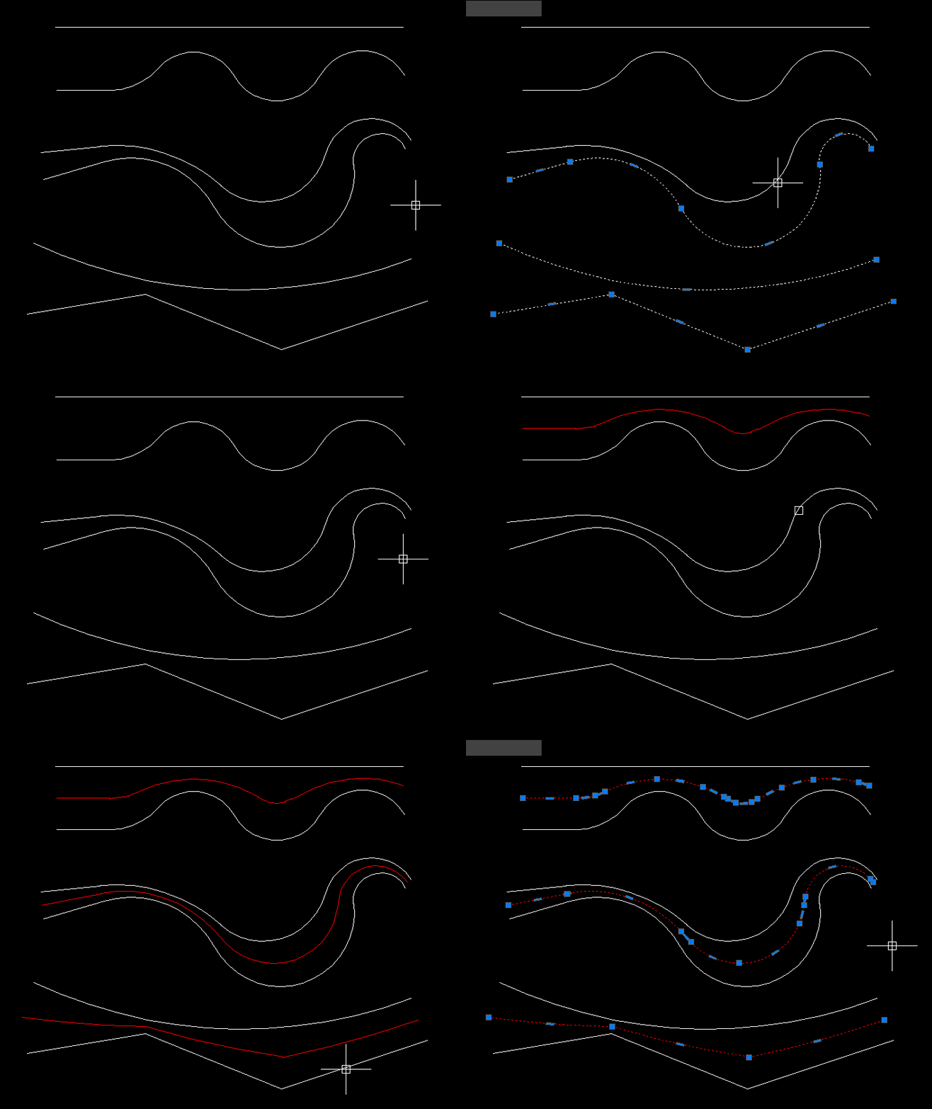
MiddleLinePolylines_2
🖱️ The command accepts a general AutoCAD selection set and requires at least two selected objects.
1️⃣ The first object in the selection set becomes the first source curve.
2️⃣ The last object in the selection set becomes the second source curve.
📐 Curve API functions read start and end points from LINE LWPOLYLINE POLYLINE ARC SPLINE ELLIPSE and similar open curve objects.
🔒 Closed curves are rejected when the start and end coordinates are equal.
➗ The source start positions are averaged to create the first centerline vertex and the source end positions are averaged to create the second.
⬇️ Z is explicitly forced to 0 because the result is a two dimensional lightweight polyline.
📦 The new LWPOLYLINE is created directly in ModelSpace through COM.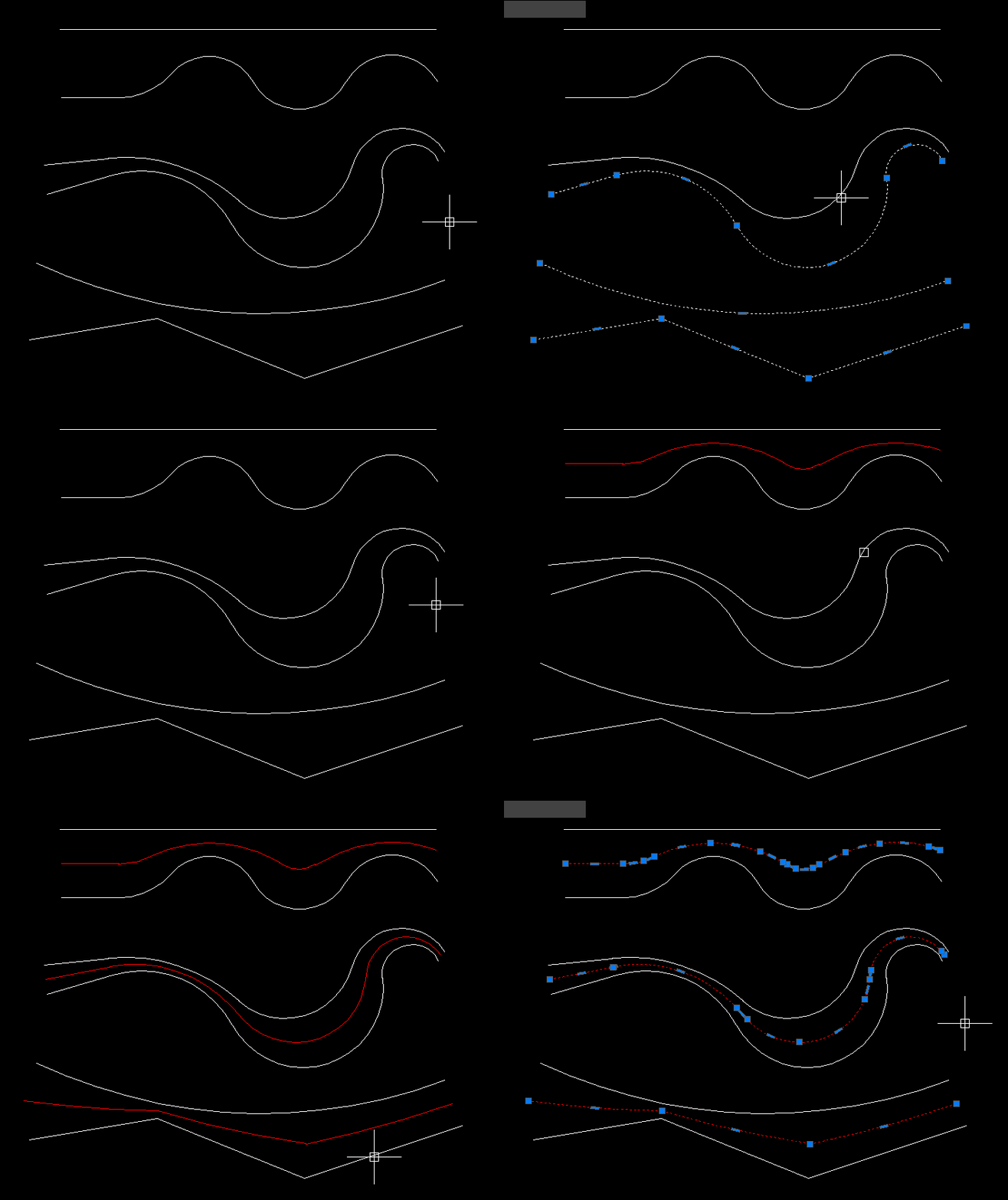
MiddleLinePolylines
🖱️ The user selects a first and second open curve and the picked sides help determine the temporary offset directions.
🌐 Selected curves are copied with VLA Copy so general supported curve types can be processed.
📏 A working offset distance is calculated from the maximum distance relationship between the two curves.
🏗️ The routine creates temporary offsets and lofts geometry from each source copy toward its offset.
🎯 Intersection style processing is then used to derive the center path.
📐 The source reports a polyline result for straight geometry and a spline result when curves are present.
🛡️ Elevation normal UCS view and AutoCAD version checks are included.
↩️ Temporary system variables are restored through the command error handler and undo group.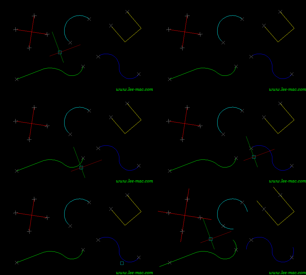
Lengthen
🎛️ The dialog opens before object selection and includes Pick Entities Window Crossing.
➡️ Extend Start and Extend End control independent endpoint extension values.
↔️ Enable Both Ends Slot activates one shared slot length that can be used on both ends.
👁️ Dynamic Drag Preview lets the user interactively adjust the both ends slot while selected objects remain highlighted.
✨ Selected entities are highlighted while the tool is active and restored when appropriate.
✅ Apply performs the current operation and keeps the tool available for further adjustment.
↩️ Undo restores the snapshot taken before the latest Apply style operation.
🧪 Debug writes a DEX_debug.txt diagnostic report into the AutoCAD TEMP folder.
💾 The dialog stores its last screen relative position in a session global.
🛡️ The header identifies the file as Civil 3D compatibility updated.InteriorPolylinesArea
🎛️ BR2P remembers the last selected radio option during the AutoCAD session.
✂️ BreakAll breaks selected LINE ARC SPLINE LWPOLYLINE POLYLINE CIRCLE and ELLIPSE geometry at intersections.
📐 Boundary Offset creates closed region style boundary results from selected planar path geometry.
🔄 Region2Polyline converts region boundaries into lightweight polyline geometry.
🧩 Combined options can run Boundary Offset plus Region2Polyline or BreakAll plus Boundary Offset plus Region2Polyline.
🧹 Keeps Closed Polylines only deletes LINE entities and open polyline geometry from a selected window while retaining closed polylines.
🔗 JoinAreas closes selected lightweight polylines converts them to regions performs ACUNION and rebuilds the result as joined polyline geometry.ExtendStartEndMultiple
📐 The routine is based on Lee Mac DoubleExtend logic and supports straight and curved polyline geometry.
🖱️ Source entities are selected before the DCL loop starts.
➡️ Extend Start and Extend End are independent values so each end can be lengthened by a different amount.
🧬 Lightweight polyline vertex and bulge calculations preserve supported curved end geometry.
✅ OK performs one apply when no Apply or Undo interaction has yet occurred and otherwise accepts the current state.
↩️ Cancel reverses all Apply operations created during the current command session.
🧱 The complete command is wrapped in an outer AutoCAD UNDO group.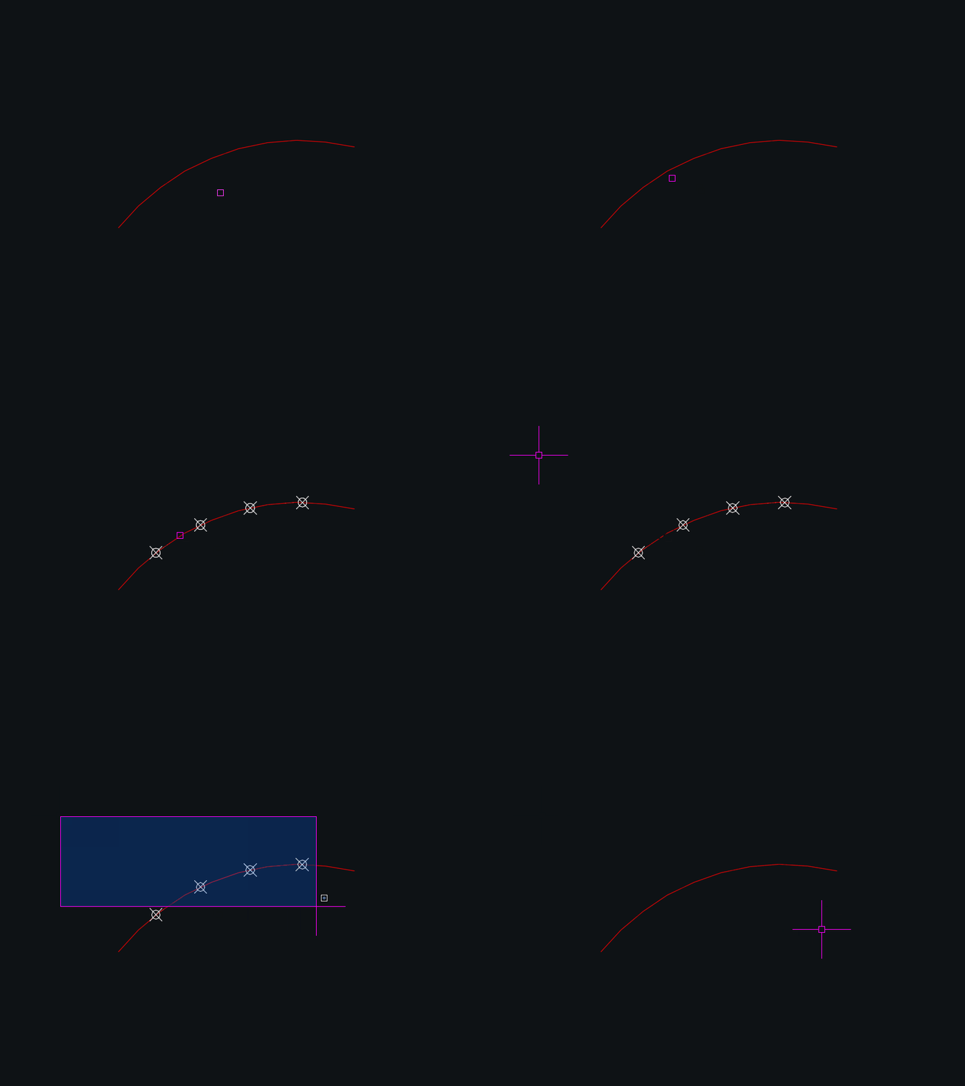
DynamicDivide
📐 The routine calculates the total curve length and divides it by the selected segment count.
👁️ Mouse movement uses temporary grpoint graphics so the user can preview the division points before clicking.
📍 A mouse click on a supported curve creates permanent AutoCAD POINT entities at the calculated intermediate distances.
➕ The plus key increases the segment count while the minus key decreases it with a minimum practical value of two.
🔢 A new segment count can also be typed and accepted with Enter or Space.
💾 The last segment count is stored through setenv under dexus:DynamicDivide and reused on the next run.
🎨 Temporary point graphics follow the current PDMODE PDSIZE and current layer color behavior.DuplicateToNewLayer
📐 The current execution workflow asks the user to select one or more compatible curve objects and creates separate right and left offsets through the VLA Offset method.
📚 The profile list automatically fills matched left and right distances for Profile_000 Profile_003 cable channel sizes and Profile_003 bundle presets.
🗂️ Place offsets on layer enables a filtered non Xref layer list and a Pick Layer From Drawing option.
🧬 When a target layer is enabled the current source moves the original object to that target layer before generating the offsets so the new offsets inherit the same layer.
🗑️ Delete original object can erase the selected source after offset generation.
🔗 Close Parallel Polylines joins one right and one left offset by calculating the shorter endpoint pairing adding two connector lines and using PEDIT Join.
➗ Create centerline polyline can generate a safe sampled centerline by averaging points on the first offset with closest points on the second offset.
📏 The safe centerline currently samples forty intervals along the first offset curve.
↩️ Apply creates one processing pass and keeps the dialog workflow active while Undo reverses the previous Apply operation.
✅ OK runs one processing pass when no Apply has yet been used then closes and commits the current undo group.
❌ Cancel reverses all Apply operations made during the current command session.DoubleOffset
📏 Standard distance mode creates one offset at the positive distance and one at the negative distance from the selected curve.
🎯 Through mode calculates the perpendicular distance between the selected through point and the closest point on the source curve and then offsets to both sides by that distance.
🔁 Through mode also provides Multiple so several through points can generate repeated pairs of offsets from the same source object.
🗑️ Erase controls whether the original source entity is deleted after offsetting.
🗂️ Layer controls whether the created offsets retain the source layer or are moved to the current AutoCAD layer.
⚙️ The current OFFSETGAPTYPE value is displayed in the settings summary.
↩️ Each selected object operation is enclosed in an AutoCAD undo mark.ConvertMultiplePolylines
🧩 ConvertMultiplePolylines combines old polyline conversion and PEDIT based joining in one AutoCAD command.
📐 Supported source objects are LINE LWPOLYLINE and old style 2D POLYLINE entities.
🔄 Old 2D POLYLINE objects are rebuilt as LWPOLYLINE entities before the final PEDIT operation.
🧬 The legacy polyline conversion preserves supported vertex coordinates widths bulges elevation closed state pline generation state layer linetype color linetype scale lineweight thickness normal and XData.
🎛️ The DCL interface provides Select entities and All entities in drawing modes together with an editable joining fuzz distance.
🔗 When the fuzz distance is greater than 0 the routine uses PEDIT Multiple Join with Extend jointype.
📌 When the fuzz distance is 0 or less the routine performs conversion through PEDIT without the Join operation.
🖱️ Selected entity mode first uses the current implied selection when available and otherwise prompts the user for objects.
🌐 All entities mode scans the drawing for LINE LWPOLYLINE and valid old style 2D POLYLINE entities.LispLoaderExtra
🧩 LispLoaderExtra v1.5.000 is a modeless AutoCAD and Civil 3D .NET loader for scanning filtering selecting loading and reloading LSP VLX FAS and DLL files from a structured CAD tool library.
🎛️ The plugin provides a dark themed WinForms interface with category and name filters search checkboxes status columns a live log pane and load controls.
🛡️ Files are loaded through the AutoCAD application context with isolated results so one failed tool does not have to stop the rest of the selected load sequence.LispLoader v1.0.000
🧩 LispLoader v1.0.000 is an AutoCAD and Civil 3D .NET startup loader that reads LoaderConfig.txt and safely processes configured LSP VLX FAS and DLL program files.
📄 One configured file failing does not intentionally stop the remaining load sequence and all results are written to the AutoCAD command line and a rolling disk log.
⚙️ The plugin starts its configured load sequence immediately when the compiled LispLoader DLL is loaded into AutoCAD.LayoutVPOverrides
🎛️ LayoutVPOverrides is an AutoLISP / Visual LISP utility for applying AutoCAD viewport layer overrides across multiple selected layouts.
🧭 It guides the user through DCL selection lists for layer groups, layers, override property, property value, and target layouts.
📐 The command is especially useful in Civil 3D sheet sets where xref layers need consistent viewport-specific Freeze, Thaw, Color, Linetype, Lineweight, Plot Style, or Transparency settings across many layouts.
🧩 It builds a VPLAYER command sequence and applies it layout-by-layout while restoring the active layout afterward.Dan_alldlls
🧩 [username]_alldlls centralizes the loading of several custom AutoCAD and Civil 3D .NET assemblies.
⚙️ Every configured assembly is passed to the native AutoCAD NETLOAD command.
🛡️ Each NETLOAD call is wrapped with Visual LISP error trapping so a failed assembly path can be collected.
📄 When one or more load attempts fail the routine overwrites load_report.txt with a FAILED TO LOAD section containing those paths.
✅ When no failure is detected the AutoCAD command line displays a successful completion message.@Dan_acaddoc
🧩 acaddoc centralizes the startup loading of hundreds of AutoCAD and Civil 3D customization tools.
🛡️ Protected loader functions wrap each load attempt so common failures can be recorded without immediately losing the complete startup report.
🧠 Diagnostic logic classifies common problems such as malformed LISP syntax missing dependencies missing files argument errors DCL problems and command context errors.
📌 The loader also blocks reentrant execution so a second copy cannot start while the first loading pass is active.
🚫 Several known problematic folders are intentionally excluded because their reactors syntax problems or nested loads can interrupt the master loading sequence.ViewportMatchOrientation
🧭 ViewportMatchOrientation is an SEO-friendly AutoCAD viewport rotation utility for paper space layout coordination.
🔄 The command switches to paper space, prompts for a source viewport, reads its AcDbViewport TwistAngle, then applies that angle to a second selected viewport.
📐 This helps match north orientation, rotated plan views, layout sheet viewports, and Civil 3D plan production view directions.
🎯 The routine is useful when multiple layouts or detail viewports must share the same rotation without manually entering viewport twist values.VportsPoly2Rectang
🪟 VportsPoly2Rectang is an SEO-friendly AutoCAD viewport clipping utility for managing rectangular and non-rectangular viewports in paper space layouts.
🔍 The routine scans layout block table records using VLA iteration, which avoids unreliable ssget layout filtering when inactive layout tabs are involved.
🔄 It identifies polygonal clipped viewports through DXF clip references and non-rectangular viewport flags, then supports converting viewport shape states.
🔐 It includes lock/unlock status, viewport filtering, select all poly/rect viewport tools, zoom-to-selected, custom clip boundary options, and persisted settings.
🎯 This is useful for layout QA, clipped viewport cleanup, Civil 3D sheet production, and paper space viewport standardization.PlotExtra
🖨️ PlotExtra is an SEO-friendly AutoCAD .NET plugin for improving layout plotting, page setup control, PDF output preparation, and plot preview workflows.
📐 The project captures layout geometry for a lightweight preview panel and exposes a custom plot dialog modeled after AutoCAD plot settings.
🧾 A dedicated log viewer command helps diagnose plot dialog actions, preview capture issues, and workflow status during testing.
🗂️ PDF project and age-tier configuration forms support project-based output management and visual organization of recently modified PDF files.
🎯 This is useful for Civil 3D plotting, AutoCAD sheet production, PDF export workflows, custom plot automation, and C# plugin UI development.PageSetupAllLayouts
🖨️ PageSetupAllLayouts is an SEO-friendly AutoCAD plot-device update routine for paper-space layouts, plot configuration cleanup, and sheet plotting preparation.
📄 The routine accesses the active document through Visual LISP ActiveX, iterates through the Layouts collection, skips Model, reads each layout ConfigName, and writes a new ConfigName.
🔁 In the current code, layouts using Canon iPF770.pc3 are changed to AutoCAD PDF (High Quality Print).pc3, while other paper-space layouts are changed to Canon iPF770V2.pc3.
🧰 Although the file comment says Copy current layout page setup to all layout tabs, the implementation specifically updates plot device names through vla-put-ConfigName rather than cloning a complete page setup object.
📌 This is useful for CAD offices migrating plotter device names, replacing outdated PC3 files, repairing broken plotting devices, and preparing Civil 3D layout sheets for consistent publishing.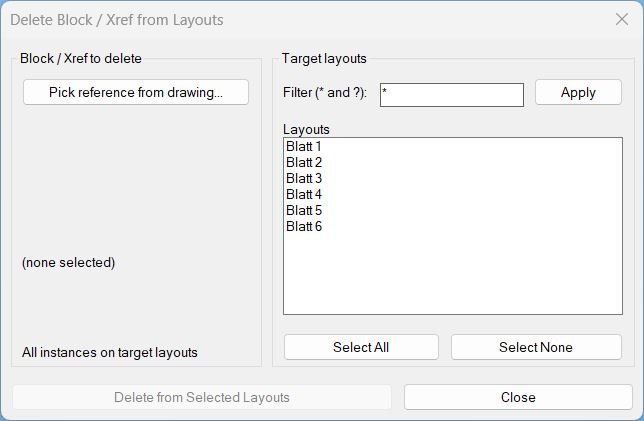
Delete2Layouts
🗑️ Delete2Layouts is an SEO-friendly AutoCAD layout cleanup tool for removing a selected block or xref reference from multiple paper-space layouts.
📋 The routine opens a custom DCL dialog named Delete Block / Xref from Layouts, where the user can pick a reference from the drawing and choose target layouts.
🔍 Layout selection supports wildcard filtering with * and ?, making it useful for large sheet sets with many layout tabs.
🧱 The delete engine scans each selected layout block, compares INSERT names to the picked block or xref name, and deletes matching instances using vlax-invoke-method Delete.
🧹 After deletion, the routine attempts a block purge for the selected name and reports the total deleted instances.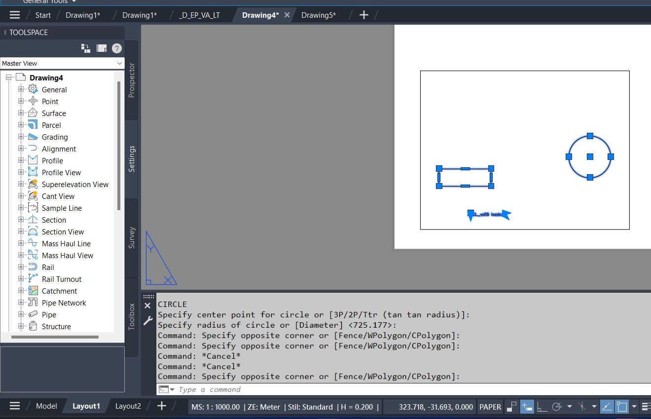
CopyPaper2Model
🔁 CopyPaper2Model is an SEO-friendly AutoCAD Paper Space to Model Space copy tool designed for layouts, viewports, and Civil 3D sheet production workflows.
📐 The routine copies selected Paper Space annotation or drafting objects, primes the chosen viewport, and uses AutoCAD CHSPACE to move the copied entities into Model Space at the correct viewport scale and position.
🖼️ The same LISP file also contains MS2PS logic for copying selected Model Space objects into Paper Space through selected layout viewports.
🧭 The tool is useful when sheet-based labels, notes, details, or construction markups must be converted back into real Model Space geometry without manually recalculating viewport scale.
📌 It includes DCL selection dialogs, layout filtering with wildcard patterns, viewport selection, viewport lock handling, and an undo-mark workflow.SelectCreateLayerFilter
🔎 SelectCreateLayerFilter is an SEO-friendly AutoCAD layer filter generator for drawings with many layers, xrefs, discipline layers, and Civil 3D production standards.
🧩 The command starts by prompting the user to select entities, extracts their layer names from DXF group code 8, removes duplicates, and uses those names as the source list for a layer Properties Filter.
🎛️ The temporary DCL dialog provides filter name, parent filter, wildcard layer filtering, multi-select layer control, horizontal scrolling for long layer names, Select All, Select None, Undo, Copy Expression, Copy Layers, Debug, Apply, and Cancel.
📋 The generated expression uses AutoCAD-style layer filter syntax such as NAME==”LayerName” OR NAME==”OtherLayer”.
🏗️ This is useful for AutoCAD and Civil 3D layer management, xref layer cleanup, project layer grouping, discipline filtering, QA review, and fast creation of custom layer filters from selected model-space objects.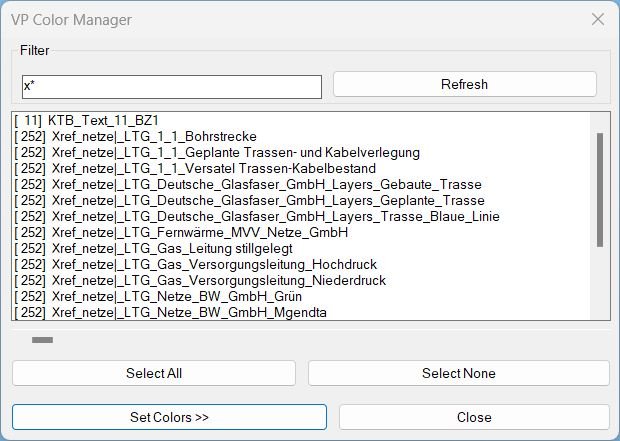
ChangeVPLayerColor
🎨 ChangeVPLayerColor is an SEO-friendly AutoCAD viewport layer color management tool for Civil 3D layout production and utility-plan presentation.
🔍 The main dialog builds a sorted layer list with current color values, a filter field, Apply and Refresh actions, Select All / Select None, and a horizontal display offset slider for long layer names.
🧩 The tool includes Config Bestand and Config Neu paginated dialogs where preset layer/color entries can be enabled or disabled before applying predefined color schemes.
📐 The VP Color Assignment dialog lists selected layers with their linetype and color popup lists, then applies the selected colors to every real viewport in the chosen target layouts using the AutoCAD VPLAYER command.
📌 This is useful for Civil 3D viewport graphics, utility line color overrides, Bestand/Neu plan styling, layout-specific plotting, and CAD production workflows that require different colors in Paper Space viewports.Reconcill_All_Layers
🧹 Reconcill_All_Layers is an SEO-friendly AutoCAD layer cleanup tool focused on unreconciled layers, layer notification control, and CAD production drawing maintenance.
🔍 The routine loops through every layer in the active document, accesses each layer extension dictionary, and removes the ADSK_XREC_LAYER_RECONCILED xrecord when it exists.
🔕 After clearing the reconciliation markers, the tool turns off AutoCAD new-layer evaluation with LAYEREVAL set to 0 and layer notification warnings with LAYERNOTIFY set to 0.
📌 This is useful for Civil 3D drawings, xref-heavy CAD files, project templates, copied DWG files, and production drawings where old unreconciled-layer warnings interrupt drafting work.
⚙️ The routine uses Visual LISP and ActiveX access to the current AutoCAD document and layer collection, making it fast and direct for all layers in the DWG.Make_layers_linetypes_draw
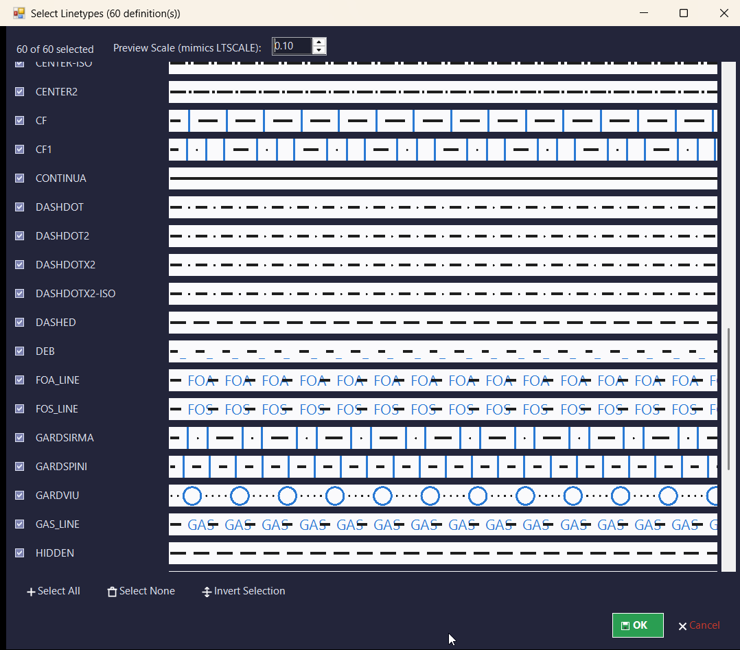
🧾 This AutoCAD linetype visualization tool scans the active drawing’s loaded linetypes and creates a graphical reference sheet.
🎛️ The main DCL dialog controls the start point, sample line length, row step, linetype scale, label offset, and MTEXT content mode.
🔎 A second linetype selection dialog supports paging, Select All, Select None, global selection, and wildcard filtering.
🧱 For each selected linetype, the routine creates or updates a layer with the same name, assigns that linetype to the layer, and draws a sample LWPOLYLINE.
📝 It then places MTEXT labels showing the linetype name, the layer name, or both side by side.
📌 The command excludes ByLayer, ByBlock, and Continuous from the generated catalog.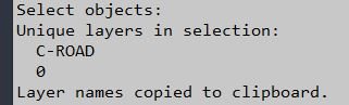
LayersName2Clipboard
📋 This AutoCAD layer extraction command asks the user to select entities, reads each entity’s DXF layer name, and builds a unique layer list.
🔎 The routine uses DXF group code 8 from entget data, which directly represents the entity layer.
🧠 Duplicate layer names are removed so each selected layer appears only once.
📄 The final output is printed in the AutoCAD command line and copied as a newline-separated text list to the Windows clipboard.
⚙️ Clipboard transfer is handled through the Windows htmlfile ActiveX object.LayerImport
🧩 This AutoCAD layer import tool reads external CSV or XML layer tables and applies the selected layer properties to the active DWG.
📥 The workflow supports full layer-state restoration including On/Off, Frozen, Frozen in Viewport, Locked, Plot, Colour, Linetype, Lineweight, Plot Style, and Description.
🎛️ The DCL dialog gives the user field-by-field control, so a drawing can import only colour, only linetype, only viewport freeze settings, or any selected property combination.
🔎 A wildcard layer filter using * and ? plus comma-separated OR matching helps isolate project layers before applying changes.
🧠 The tool includes undo-state snapshots so the user can apply changes, review the result, and restore the previous layer state when needed.
🗂️ Predefined folder management and DWG-name matching help automate common Civil 3D project folders and repeatable layer standards workflows.LayerFilterFreezeThawOnPlotVPFreeze
❄️ LayerFilterFreezeThawOnPlotVPFreeze is an SEO-friendly AutoCAD layer filter manager for applying multiple layer-state, plot-state, and viewport-state actions from one DCL dialog.
🧱 The tool reads layer filter definitions from AutoCAD’s layer filter dictionaries and resolves useful layer-name patterns into actual drawing layers.
🎛️ Standard actions include Freeze, Thaw, On, Off, Lock, Unlock, Plot, and No Plot, with paired exclusive toggles to prevent contradictory settings.
🖼️ Viewport actions support VP Freeze and VP Thaw by selecting a paper-space viewport, temporarily unlocking it if necessary, editing ACAD XDATA layer entries, and refreshing the viewport.
📌 This is useful for Civil 3D sheet preparation, viewport-specific layer visibility, xref plotting control, layer filter execution, and CAD production layout management.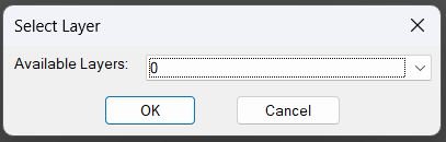
ChangeLayerToSelected_vs.01
🗂️ ChangeLayerToCurrent is an SEO-friendly AutoCAD layer management tool for changing selected objects to a selected drawing layer.
🔍 The command builds a temporary DCL dialog, lists all layers, supports a filter text box, and remembers the last selected layer and filter using environment variables.
🎯 A Pick Layer workflow lets the user select an existing object and reuse its layer as the target layer.
📋 A Copy Layer Name helper sends the chosen layer name to the Windows clipboard through PowerShell/clip logic.
🧠 The optional Keep original properties mode captures effective linetype, linetype scale, and lineweight/width before moving objects, then reapplies those values after the layer change.ChangeLayerToCurrent
🗂️ ChangeLayerToCurrent is an SEO-friendly AutoCAD layer management tool for changing selected objects to a selected drawing layer.
🔍 The command builds a temporary DCL dialog, lists all layers, supports a filter text box, and remembers the last selected layer and filter using environment variables.
🎯 A Pick Layer workflow lets the user select an existing object and reuse its layer as the target layer.
📋 A Copy Layer Name helper sends the chosen layer name to the Windows clipboard through PowerShell/clip logic.
🧠 The optional Keep original properties mode captures effective linetype, linetype scale, and lineweight/width before moving objects, then reapplies those values after the layer change.NamespaceFix
🛠️ NamespaceFix is an SEO-friendly AutoCAD AutoLISP namespace repair tool for drawings or startup environments where another script corrupts the global * symbol.
⚠️ The source comments identify the root cause as a separate pltools-eng6.lsp routine using (setq * …) as a variable name, which overwrites AutoLISP’s built-in multiplication operator.
🔄 The utility installs a command-ended reactor and repairs * after command completion, especially after SAVE/QSAVE workflows where the conflicting routine is loaded by a save reactor.
🧠 The repair attempts to rebuild Visual LISP built-ins with vl-load-com, then falls back to the internal acad_* function pointer when available.
📌 This is useful for Civil 3D startup suites, production CAD environments, debugging broken AutoLISP expressions, and stabilizing tools that depend on normal arithmetic behavior.ChangeBackgroundColor
🎨 ChangeBackgroundColor is an SEO-friendly AutoCAD background color manager for CAD users who switch between black, white, grey, and custom workspace visibility setups.
🧰 The BGDCL dialog is created dynamically as a temporary DCL file and lets the user apply one global color or assign different colors to Model Space, Paper Space, and Block Editor.
👁️ The routine updates display readability by changing crosshair color, AutoTracking vector color, and AutoSnap marker color according to the selected background.
🧱 Block Editor background is handled through the BEditBackground environment setting using a BGR decimal value, avoiding ARG file patching or registry edits.
↩️ The dialog stores a snapshot of the current colors and restores it if the user cancels.Text2Multileader_2
📐 Text2Multileader_2 is an SEO-friendly AutoCAD text-to-MLeader conversion routine that uses a line or polyline as a leader placement template.
🔤 It collects selected TEXT and MTEXT objects, sorts their text content by insertion point, concatenates the strings, and calculates the widest text bounding box for MLeader width.
📍 Instead of asking the user to pick two leader points manually, the tool reads the start and end points from a selected LINE or from the first and last coordinates of a selected polyline.
🧹 After creating the MLeader, it deletes the selected guide entity and the source text objects, leaving a clean MLeader annotation in the drawing.
📌 This is useful when users sketch or already have leader guide geometry and want to convert that geometry plus text into proper AutoCAD MLeader annotations.SetupOverriteDimStyles
🧰 SetupOverriteDimStyles is an SEO-friendly AutoCAD property matching and drafting standards utility for setting current annotation and workspace styles from an existing drawing object.
📌 The routine reads current CLAYER, TEXTSTYLE, DIMSTYLE, and CMLEADERSTYLE values, then compares them with the layer and annotation styles extracted from the selected object.
📊 A dynamic DCL interface presents a 4-column matrix: current workspace settings, current quantities, selected object style/name, and selected quantities.
🧠 It supports MULTILEADER, LEADER, TEXT, MTEXT, and DIMENSION source entities, making it useful for Civil 3D production drawings, CAD standard enforcement, annotation cleanup, and rapid style switching.MLeaderExtra
MLeaderVertexTool is a Civil 3D-ready AutoCAD .NET Framework plugin for editing multileader geometry by adding a bend or inflection vertex to an existing MLeader. The service reads the selected MLeader, identifies the editable leader and leader-line index, appends a duplicate of the tail vertex when needed, replaces the previous tail with the picked bend point, regenerates the drawing, and reports success or failure. The package also includes a modeless WinForms UI with selection, preview/highlight, log viewing, copy log tools, and build metadata designed to avoid AutoCAD DLL-lock rebuild problems.
Xline2Poly
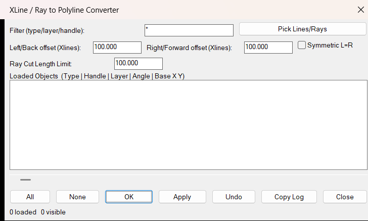
Xline2Poly is an AutoLISP utility that converts infinite XLINE entities and semi-infinite RAY entities into finite two-vertex LWPOLYLINE objects. It provides a temporary DCL interface for selecting objects, filtering by type/layer/handle, configuring conversion distances, applying symmetric offsets, copying logs, and performing undo.
The tool is useful when construction rays or xlines need to be converted into regular editable polyline geometry for documentation, trimming, quantities, or downstream CAD workflows.
Poly2Xline
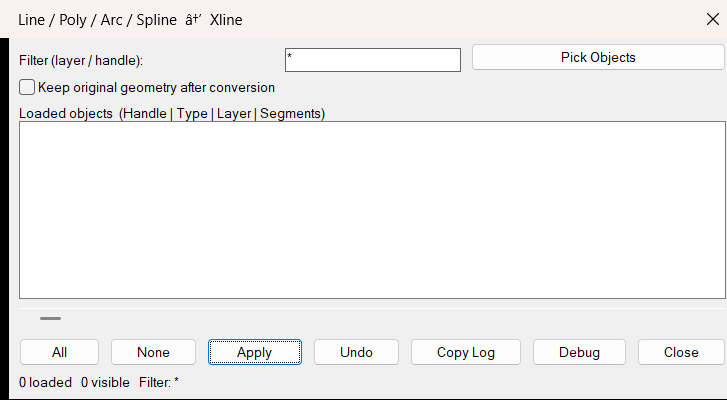
Poly2Xline is an AutoLISP utility for converting finite AutoCAD curve geometry into construction XLINE objects. It supports LINE, LWPOLYLINE, POLYLINE, ARC, and SPLINE selections, converts every extracted segment into one XLINE, and offers a dialog-based workflow with filtering, multi-selection, undo, debug reporting, and settings persistence.
The tool is useful when design geometry needs to be converted into infinite construction/reference lines while preserving key object properties such as layer, color, linetype, linetype scale, and true color.
ParallelPipes.NET
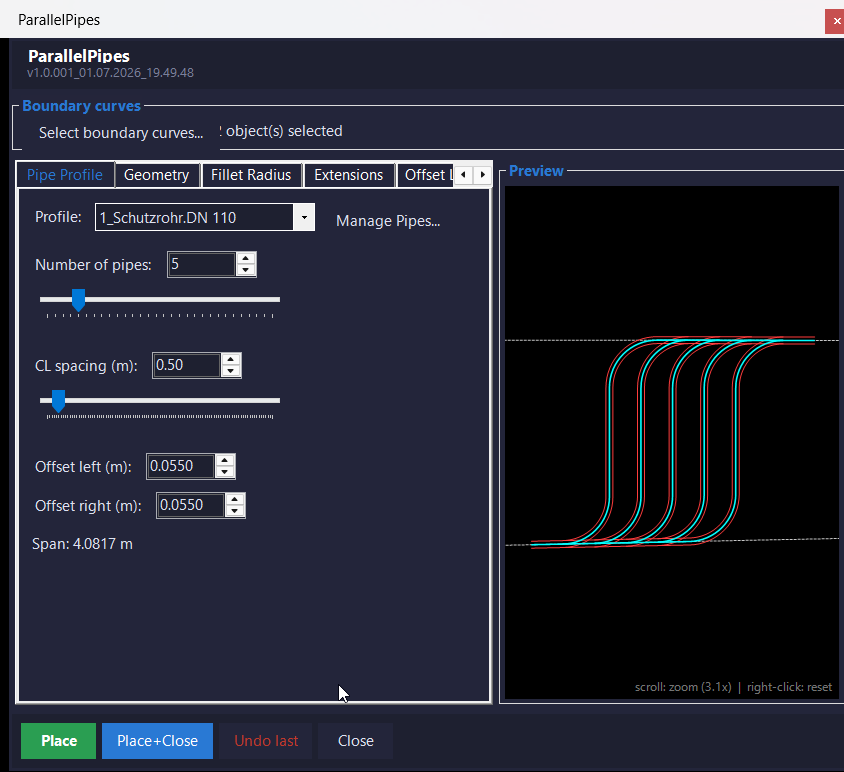
ParallelPipes.NET is a managed C# / .NET Framework 4.8 port of the original ParallelPipes.lsp workflow for AutoCAD and Civil 3D 2024. It replaces the old DCL and grread interface with a modeless WinForms tool window and a TransientManager-based live preview, while keeping the core engineering logic for parallel pipe placement, tangent fillet construction, offset generation, layer handling, and placement history.
The VTPCS command opens a tabbed interface where the user selects boundary curves, chooses a pipe profile, edits pipe count and spacing, controls fillet radii and extensions, selects output layers, previews the solved bundle, and commits the resulting pipe geometry to the DWG.
30ParallelExisting
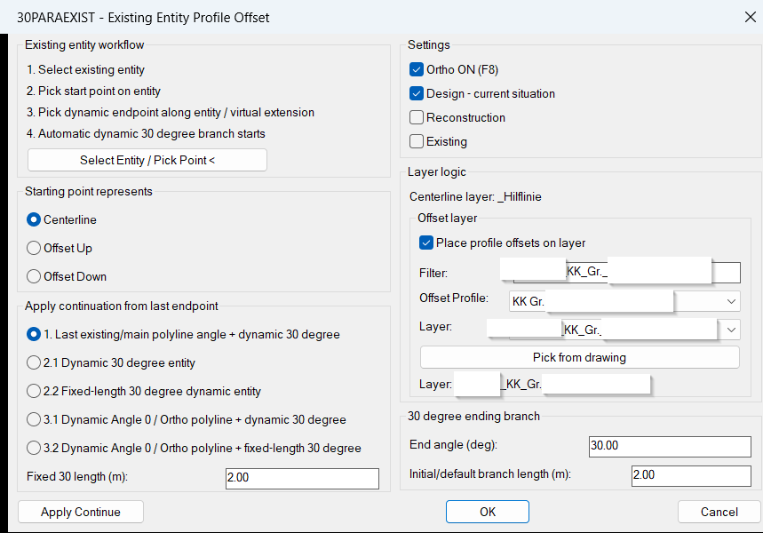
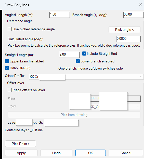
📘 30ParallelExisting builds civil utility profile geometry from an existing AutoCAD entity. It uses selected-entity following, native OFFSET behavior, Profile_002 profile presets, centerline and offset route management, dynamic 30 degree branches, full-route offset rebuilds, Apply continuation modes, and design reconstruction existing layer logic for Civil 3D production drawings.
Lin_Shx_Loader
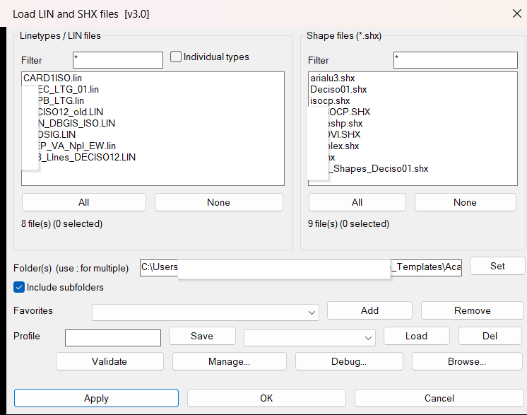
Lin_Shx_Loader opens an embedded DCL dialog for browsing, filtering, validating and loading AutoCAD linetype resources. The tool can work in LIN file mode, where complete .lin files are loaded, or in individual linetype mode, where linetype names and descriptions are parsed from all discovered LIN files and selected one by one.
The utility also handles SHX shape files, supports recursive folder scanning, allows semicolon-separated multi-folder search paths, and remembers favorites and named profiles between sessions. It is designed for CAD standards folders where many project-specific LIN and SHX resources must be loaded quickly into the current drawing.
30Parallel
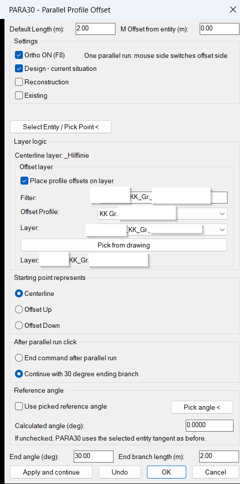
📘 30Parallel creates profile-based parallel polylines for AutoCAD and Civil 3D utility drafting. It supports PARA30 and 30PARA commands, centerline or offset start modes, profile offset presets, automatic or selected layer logic, dynamic preview, chamfer joining, and Apply-based continuation with 30 degree branch options.
30Degree
Comming soon …ReplaceBlock
🔄 ReplaceBlock provides a fast dialog-based workflow for changing existing INSERT block references to another block definition already available in the current DWG file.
🧩 The routine first asks the user to select block references. It then scans the drawing block table, builds a sorted list of available block names, and displays a temporary DCL dialog named Replace Block with a filter field and a popup list.
🔍 The filter field supports quick block-name searching by matching typed text against the available block list. After a replacement block is selected, the tool inserts a new block reference at each original block insertion point, copies the original X scale, Y scale, Z scale, rotation, layer, and color, and then deletes the previous block reference.
🛡️ Edits are wrapped inside an AutoCAD undo mark so the replacement operation can be reverted safely with one UNDO action.
RenameBlockList
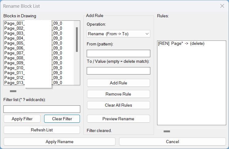
🧩 RenameBlockList provides a practical AutoCAD block management dialog for renaming many block definitions in one controlled operation. The tool scans the active drawing for editable block names, displays them in a DCL list, and lets the user filter block names with AutoCAD wildcard patterns such as * and ?.
🔍 The utility supports three rule modes: Rename, Add Prefix, and Add Suffix. Rename mode can replace matched text, remove matched text when the replacement value is empty, and correctly handles mid-string patterns such as *word*. Prefix and suffix modes add consistent naming standards to all currently visible filtered blocks.
🧠 The workflow is designed for CAD managers and production users who need to clean block naming, standardize imported block libraries, remove unwanted text fragments, or add project-specific naming prefixes and suffixes without manually renaming each block through the standard AutoCAD rename dialog.
📋 Before applying changes, the Preview Rename button opens a result dialog showing the old name and the proposed new name. The final Apply Rename action works only on the filtered visible block list, which provides an extra safety layer for targeted batch updates.
CopyRenameBlockChangeLayer
🧩 CopyRenameBlockChangeLayer is an AutoCAD AutoLISP block utility based on the copy and rename block-reference workflow, extended with a DCL dialog for selecting a new block name and target layer.
🔄 The command can create a renamed copy of a selected block reference or rename the selected reference to a duplicated block definition, avoiding a global rename of every original block reference.
🧠 ObjectDBX cloning is used to duplicate the block definition safely, rename it, then copy it back into the active drawing under the new block name.
📌 Dynamic block properties are preserved by reading the dynamic property values before the rename and restoring them after the new block definition is assigned.
🎨 After the new block is created, the selected/new block reference can be placed on the chosen layer and the internal block entities can be forced to the same layer with color, linetype, and lineweight set to ByLayer.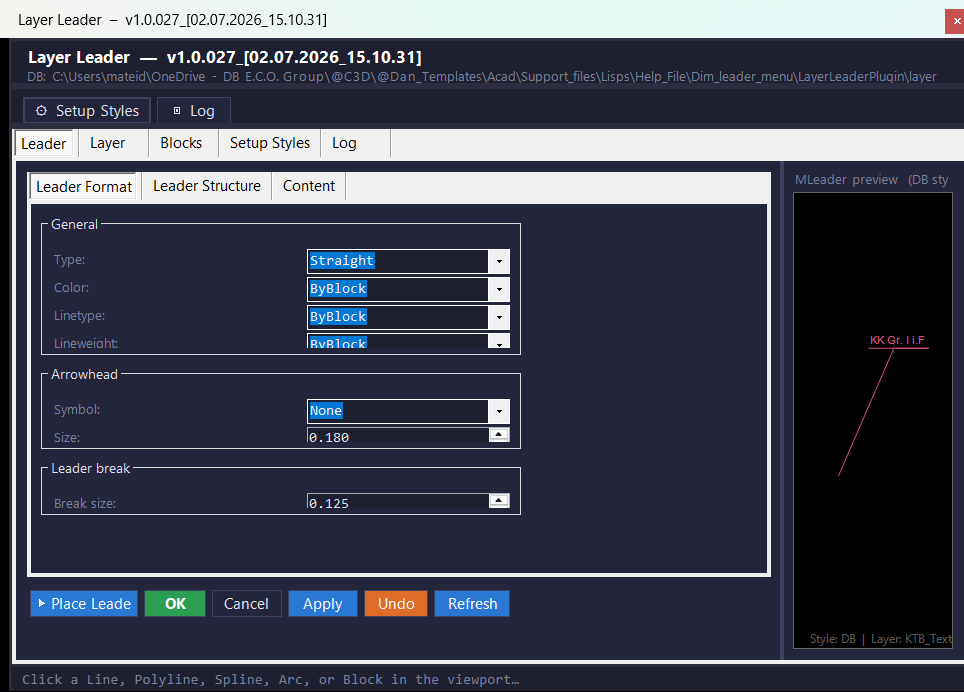
LayerLeaderPlugin
🚀 LayerLeaderPlugin is a production-focused AutoCAD Civil 3D plugin that automates MLeader label placement based on layer rules, block visibility rules, and drawing standards.
📌 The plugin loads a modeless WinForms panel that can stay open while the user works in Model Space or Paper Space. It reads layer_database.json and block_database.json from the DLL folder, displays editable label rules, and places MLeader annotations using the configured DB MLeader style.
🧩 The Leader workflow supports selecting drawing entities, picking arrowhead and text points, and placing a linked label that can be refreshed later. The Layer tab manages layer-to-label mappings, while the Blocks tab maps dynamic block names and visibility-state patterns to clean display labels.
🧠 The project also includes integrated AutoLISP helpers for dimension-style override cleanup and background-mask workflows, giving CAD managers one combined tool for annotation placement, style control, and Civil 3D production cleanup.
🔐 Version 1.0.027 includes a build-path fix for long OneDrive and support-file folders by using a short intermediate build folder, helping Visual Studio avoid classic Windows path-length failures during MSBuild generation.
NavvCubeDisplayOffOn
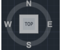
📘 NavvCubeDisplayOffOn is an SEO-friendly AutoCAD AutoLISP command for quickly refreshing or restoring the Navigation Cube display in the active drawing session.
🧭 The routine gets the active AutoCAD document through Visual LISP COM automation, then sends two NAVVCUBEDISPLAY command calls to AutoCAD. This creates a simple one-command workflow for users who need to bring the navigation cube display back into the desired visible state.
🔄 The uploaded code performs a two-step display reset by sending value 1 and then value 3 to the NAVVCUBEDISPLAY command. This is useful when the navigation widget visibility or screen state needs a fast manual reset from the command line.
🧰 The tool is intentionally lightweight. It does not open a dialog, does not ask for object selection, and does not modify drawing geometry. It only targets the AutoCAD navigation cube display setting.
📌 This utility is useful for AutoCAD and Civil 3D users who frequently switch workspaces, clean up screen layouts, prepare screenshots, or need quick access to the navigation cube display controls.
CopyMove2MidPoint_vs.01
🚀 MTM2 provides a fast midpoint-to-midpoint workflow for AutoCAD drafting and Civil 3D production drawings.
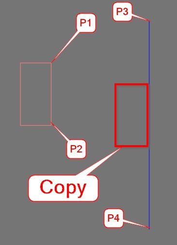
📌 The tool lets the user select one or more objects, define a source reference with two picked points, define a destination reference with two picked points, and then move or copy the selected objects by the calculated midpoint vector.
📐 The source midpoint is calculated from the Y values of P1 and P2 while preserving the X and Z values from P1. The destination midpoint is calculated as a full 3D midpoint from P3 and P4.
🔄 The resulting translation vector is transformed from UCS to WCS before applying the move or copy operation, making the workflow suitable for drawings using custom UCS orientations.
🧱 Objects on locked layers are skipped to avoid modification errors during batch processing.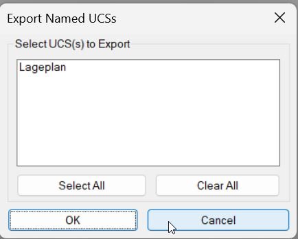
Export_Import_MS_UCS
📘 Export_Import_MS_UCS is an SEO-friendly AutoCAD UCS export and import tool for managing named User Coordinate Systems in model-space drawings.
📤 The export workflow collects named UCS records from the current drawing and writes them to a portable .ucs text file. This allows project UCS definitions to be reused in another DWG without rebuilding coordinate systems manually.
📥 The import workflow reads UCS definitions from a previously exported .ucs file and recreates them in the active drawing. If an imported UCS name already exists, the routine creates a unique name by appending underscores to avoid overwriting the existing UCS definition.
🗂️ The tool remembers the last-used UCS folder through the Windows Registry and defaults to the current drawing folder when no previous UCS folder is available. This keeps repeated export and import operations faster in project folders.
🧭 The workflow is useful for Civil 3D layouts, coordinate control drawings, UCS_Lageplan management, model-space orientation transfer, xref coordination, plan production, and CAD standardization between project files.
XrefDrawingOrder
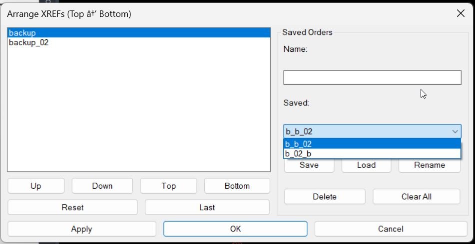
🧩 XrefDrawingOrder scans the active AutoCAD drawing for loaded XREF block definitions and presents them in an ordered list titled Arrange XREFs Top to Bottom.
🔄 The user can move xrefs Up, Down, Top, or Bottom, then apply the selected draw order without manually selecting every xref reference in model space.
📌 The command uses AutoCAD DRAWORDER logic to move each xref underneath the previous xref in the ordered list, creating a controlled stacked xref display.
💾 The utility also stores the last applied order inside the drawing with a Named Object Dictionary XRECORD, making the previous order available again with the Last button.
🗂️ Named saved orders can also be stored in MXR_XrefOrders.txt, making it possible to save, load, rename, delete, and clear reusable xref ordering presets.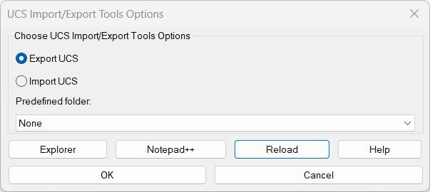
ExpImpUCS
🧭 ExpImpUCS is an SEO-friendly AutoCAD UCS import and export tool for managing named User Coordinate Systems in production drawings.
📤 In export mode, the tool scans all named UCS definitions in the active drawing and writes them to a portable .ucs text file.
📥 In import mode, the tool reads .ucs files line by line and creates or updates named UCS definitions in the active drawing.
🗂️ The exported UCS format stores the UCS name, origin point, X-axis point, and Y-axis point as Name;P1;P2;P3, making the file easy to reuse and inspect.
🧠 The latest importer uses COM-based UserCoordinateSystems logic to update UCS records directly, avoiding command-line UCS calls that can freeze or interrupt automated workflows.
📌 This is useful for Civil 3D layout drawings, coordinate control, Lageplan UCS setup, repeated project folders, Xref orientation workflows, and CAD production environments where UCS consistency is important.AreaCalc
📐 AreaCalc is an AutoCAD and Civil 3D AutoLISP utility for calculating and reporting areas from closed drawing geometry. It is useful for CAD drafting, quantity takeoff, land development plans, hatch based measurement, closed polyline area reporting, and Civil 3D production drawings where area values need to be labeled and exported quickly.
🔍 The AC command filters the selection to supported area-capable objects, including closed polylines, circles, ellipses, regions, splines, and hatches. The routine checks that selected curve objects are closed, calculates each area with the AutoCAD AREA object workflow, stores the total, and determines label locations from object bounding boxes.
🧮 The Area Calc v2.1 dialog lets the user set a label prefix, starting label number, source units, target conversion units, optional second conversion units, and decimal precision. The default source unit is driven by the INSUNITS variable when available, with a fallback default when INSUNITS is zero.
📊 AreaCalc can output results as placed LineText, a native AutoCAD table, a TXT report, or a CSV report. TXT and CSV reports are written to the AutoCAD support path near ACAD.PAT and opened in Windows Explorer after creation.
🧩 When field output is enabled, supported report types can use AutoCAD object fields so area values remain linked to the source objects. This makes the workflow useful when the drawing may still change after the first calculation.
LinetypeWithCharacters2
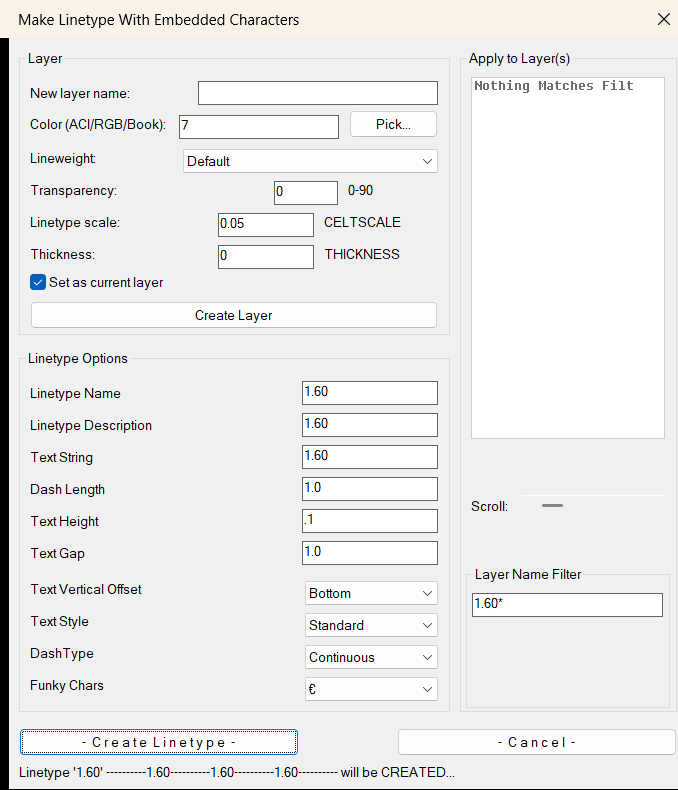
🧵 LinetypeWithCharacters2 is an AutoCAD AutoLISP utility for creating or redefining custom linetypes that contain embedded text characters.
🔤 The tool builds a temporary LIN definition using the selected text string, text style, dash pattern, text height, text gap, and vertical offset, then loads the linetype through the AutoCAD command workflow.
🎨 The dialog also includes a layer creation and update section with ACI, RGB, Color Book input, Pick color, lineweight, transparency from 0 to 90, CELTSCALE, THICKNESS, and optional Set Current logic.
📂 Users can apply the generated linetype to one target layer or multiple selected layers from a filtered layer list, making the tool useful for CAD standards, utility linework, Civil 3D drafting, signage lines, fence lines, cable routes, and annotation-based linetypes.
LinFileDraw_vs.01
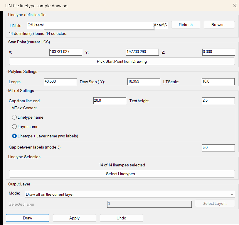
📘 LinFileDraw helps AutoCAD and Civil 3D users preview, test, and document linetypes from external LIN definition files directly inside the drawing.
🔍 The routine reads linetype names from a selected *.LIN file, displays the available definitions in an embedded DCL interface, and lets the user choose which linetypes should be drawn as sample rows.
📐 For every selected linetype, the tool creates a horizontal LWPOLYLINE sample and optional MText labels. The generated geometry respects the current UCS for the start point, row direction, object placement, normal vector, and text direction.
🏷️ Output can be organized automatically by linetype layer, placed on the current layer, or directed to a selected existing layer. This makes the routine practical for creating CAD linetype legends, linetype QA drawings, template checks, and Civil 3D drafting standards documentation.
💾 The dialog remembers accepted settings, selected linetypes, and dialog positions in a CFG file, so the same LIN file workflow can be reopened quickly in later AutoCAD sessions.
LinFileDraw
📘 LinFileDraw helps AutoCAD and Civil 3D users preview, test, and document linetypes from external LIN definition files directly inside the drawing.
🔍 The routine reads linetype names from a selected *.LIN file, displays the available definitions in an embedded DCL interface, and lets the user choose which linetypes should be drawn as sample rows.
📐 For every selected linetype, the tool creates a horizontal LWPOLYLINE sample and optional MText labels. The generated geometry respects the current UCS for the start point, row direction, object placement, normal vector, and text direction.
🏷️ Output can be organized automatically by linetype layer, placed on the current layer, or directed to a selected existing layer. This makes the routine practical for creating CAD linetype legends, linetype QA drawings, template checks, and Civil 3D drafting standards documentation.
💾 The dialog remembers accepted settings, selected linetypes, and dialog positions in a CFG file, so the same LIN file workflow can be reopened quickly in later AutoCAD sessions.
XrefOffsetLayer
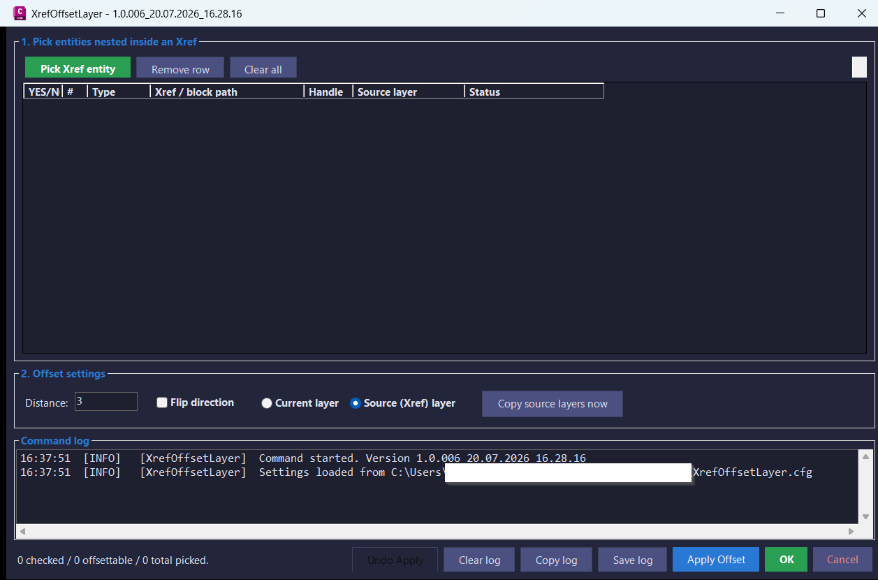
🚀 XrefOffsetLayer is an AutoCAD and Civil 3D .NET plugin for offsetting supported curve entities that are nested inside attached Xrefs, including nested Xref chains.
Run
XREFOFFSETLAYER,XREFOFFSETLAYER_006, or the short aliasXOLto open a modeless picker dialog. The user can pick Xref entities, set an offset distance, flip the offset side, choose a target layer strategy, and apply offsets into the active drawing without editing the source Xref.The plugin is designed for CAD production workflows where Xref geometry needs to be referenced, offset, and recreated in the host drawing while preserving a clear visual process and diagnostic log.
ReplaceBlockList
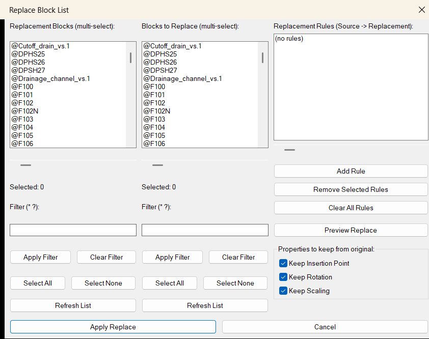
🔁 ReplaceBlockList is an AutoCAD block replacement utility designed for batch block management inside production drawings. It provides a visual DCL dialog with two synchronized multi-select block panels: one for replacement blocks and one for blocks that should be replaced.
🧱 The tool scans the active drawing block table, lists normal block definitions, and excludes xrefs, layout blocks, and anonymous block names from the selectable definition lists. Users can filter both lists with wildcard patterns, select multiple items, create replacement rules, preview affected instance counts, and apply all rules in one controlled operation.
📋 Each rule is stored as a clear
Source -> Replacementpair. When applied, the routine finds source block references drawing-wide, copies the first inserted instance of the selected replacement block, transfers selected geometric properties from the original source reference, and deletes the old source block reference.⚙️ The optional preserve toggles allow the user to keep the original block insertion point, rotation, and effective X/Y/Z scale. This makes the command useful for symbol swaps, title block cleanup, CAD standards migration, drawing modernization, and large-scale block replacement tasks.
💾 The tool stores filters, replacement rules, and keep-property settings in a temporary configuration file so the same replacement setup can be reused between sessions.
LayersImportExport
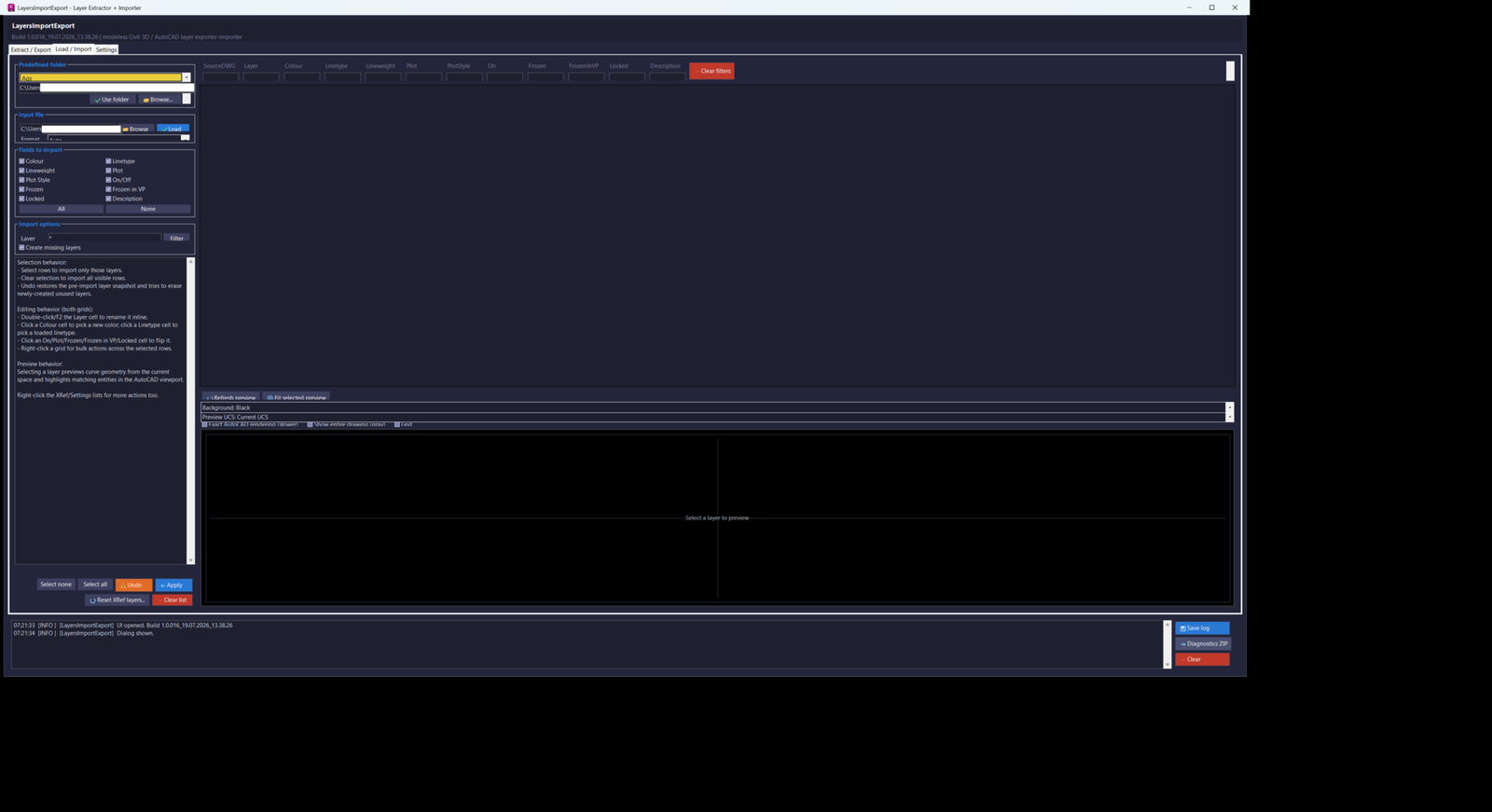
LayersImportExport_016 is a combined C#/.NET replacement for the legacy LayerExtractor.lsp and LayerImport.lsp workflows. It provides one modeless, resizable AutoCAD and Civil 3D 2024 dialog with Extract / Export, Load / Import, and Settings tabs.
The Export workflow extracts layer definitions from the current drawing or from a directory of DWG files. Directory extraction runs in the background with progress reporting and cancellation. Users can include host-drawing layers, include Xref-dependent layers, restrict output to selected Xrefs, scan subfolders, choose individual property fields, filter the visible layer rows, edit pending values in the grid, copy rows as CSV, apply selected edited rows back to the current drawing, or export the result as UTF-8 CSV or XML.
Exportable and importable properties include layer name, colour, linetype, lineweight, plot state, plot style, on/off state, frozen state, viewport-frozen state, locked state, and description. Directory exports may also include the source DWG name. Colour values support both AutoCAD Colour Index values and true-colour values in TC:R,G,B form.
The Import workflow loads CSV or XML layer files, filters the rows, lets users select the property fields to apply, and can create missing layers, update existing layers, or perform both operations. The Apply process reports created, updated, skipped, and failed counts, displays cooperative progress and cancellation, and stores a layer snapshot for Undo.
Xref workflows include reading Xref-dependent layers, filtering by Xref owner, picking an Xref directly from the drawing, resolving selections made on nested entities or attributed content, naming the export after the selected Xref, previewing nested Xref geometry, and resetting local Xref-layer overrides from the resolved source DWG. Reset XRef Layers opens the external drawing as a read-only side database and restores matching Xref layer definitions, with confirmation and Undo support.
Both layer grids support inline or click-based editing. Users can rename pending layer rows, choose ACI or true colour, select loaded linetypes, choose standard AutoCAD lineweights, and toggle On, Plot, Frozen, Frozen in VP, and Locked states. Multi-row edits apply to the full selected row set. Per-column filters use case-insensitive text matching or explicit wildcard patterns.
The preview system includes a fast interactive GDI+ geometry preview and an optional Exact AutoCAD rendering mode backed by the AutoCAD GraphicsSystem. Users can zoom, pan, double-click to fit, refresh, fit the selected layer, change preview background, choose WCS, Current UCS, or a named UCS, toggle a grid, display the complete current space as gray context, and show the selected layer in its resolved colour. Build 016 re-enables exact rendering and adds detailed initialization, rebuild, entity-added, entity-skipped, context, and stack-trace diagnostics.
The Settings tab manages a schema-versioned ProjectFolders.json database shared by Export and Import. Project folders can be added, updated, renamed, duplicated, deleted, reordered, opened in Explorer, and assigned as default Export or Import locations. The database auto-saves, accepts the legacy bare-array format, backs up unreadable files before reseeding defaults, and works with the persistent LayersImportExport.cfg settings file.
The modeless interface includes viewport highlighting, context menus, generated button icons, responsive DPI-aware layouts, a live application log, log copying, saved log files, and diagnostics ZIP creation. The project targets .NET Framework 4.8 and uses build-numbered assembly and command names so multiple test builds can be NETLOADed side by side.
ChangeBlockLayer
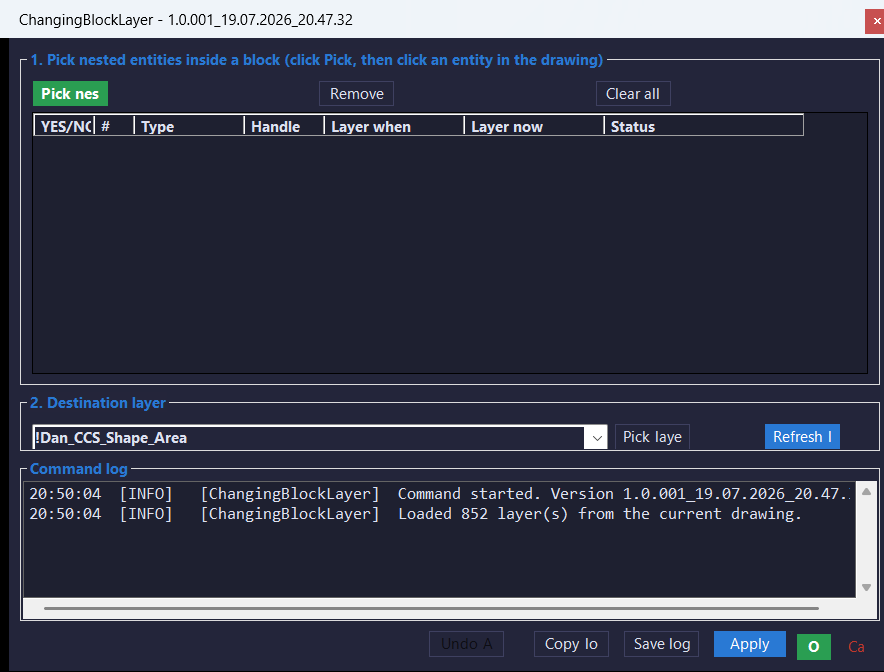
ChangingBlockLayer_001 provides a modeless AutoCAD and Civil 3D 2024 workflow for changing the layer of entities nested inside block references. The project is written in C# for .NET Framework 4.8 and uses a build-numbered DLL and primary command so multiple numbered test builds can be NETLOADed side by side without assembly-name or command-name conflicts.
The tool uses Editor.GetNestedEntity to obtain the real ObjectId of the selected nested entity together with its chain of containing block references. It reverses the container chain, appends the entity ObjectId, builds a FullSubentityPath, and highlights only the selected nested piece in the viewport instead of highlighting the complete outer block reference.
Users can click Pick nested entity repeatedly to accumulate multiple candidates in a modeless grid. Each row displays an Apply checkbox, row index, entity type, handle, layer when picked, current layer, and processing status. Rows can be reviewed, individually enabled or disabled, removed, or cleared before any drawing change is committed.
The destination layer is selected from an autocomplete dropdown populated from the current drawing’s LayerTable. Users can refresh the layer list or click Pick layer from entity and select either a top-level entity or an entity nested inside a block to use its layer as the destination. Apply validates that the typed or selected layer exists before changing any entity.
Each selected entity’s container chain is checked for externally referenced block definitions. Entities inside Xrefs are marked INSIDE XREF (not modifiable), shown as protected rows, automatically unchecked, and excluded from Apply so the command does not report a change that cannot be written back to the referenced drawing.
Apply changes only checked, modifiable rows and leaves the dialog open. OK performs the same confirmed layer change and then closes the form. Undo Apply restores the original layers from the latest Apply operation during the current dialog session. Remove row and Clear all also remove the corresponding nested-subentity highlights.
The command log records selections, handles, entity types, original and destination layers, skipped Xref rows, errors, Apply totals, and undo results. The log can be copied to the Windows clipboard or saved as a timestamped diagnostic text file in the ChangingBlockLayer application-data folder.
Entities2Layers
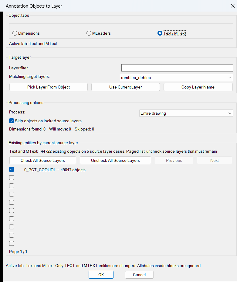
Entities2Layers v1.5.102 provides a dialog-based workflow for moving annotation objects to an existing AutoCAD layer. The tool is designed for AutoCAD and Civil 3D production drawings where dimensions, multileaders, text, and mtext objects need to be reorganized by layer without manually selecting and editing each entity.
The command opens a generated DCL interface with separate Dimensions, MLeaders, and Text / MText tabs. Users can filter the target-layer list, pick a target layer from an object, use the current layer, copy the selected layer name, choose a drawing scope, skip objects on locked source layers, and enable or disable individual source layers before applying the move.
The dialog reports how many matching objects were found, how many will move, and how many will be skipped. Source-layer cases are counted and displayed in a ten-row paged checklist with locked-layer and target-layer indicators. Settings including the selected object category, target layer, layer filter, processing scope, locked-layer option, source-layer choices, and dialog position are saved to an Entities2Layers configuration file in the user application-data folder.
The current version uses an optimized sort-and-group counting pass for drawings containing large numbers of annotation entities. Live found, move, and skip totals are derived from the existing per-layer case list instead of triggering a second full drawing scan after every dialog interaction. Named, guarded source-row handlers and defensive dialog-state validation prevent a malformed row or unusual entity from closing the dialog.
Entity counting, collection, movement, initialization, and live dialog callbacks use guarded Visual LISP error handling. Unreadable or unusual entities are skipped and reported instead of terminating the command. The move operation updates DXF group code 8, refreshes each changed entity, and wraps the modifications in an AutoCAD undo mark.
ExplodeLinetype
ExplodeLinetype provides an AutoCAD and Civil 3D AutoLISP workflow for converting selected TEXT and MTEXT objects into editable linework. The routine is based on the LINEXP modification of the Express Tools TXTEXP workflow and uses a temporary WMF export and import process to reproduce text outlines as drawing entities.
The primary ExplodeLinetype command runs LINEXP and then applies CHPROP to the previous selection set. The resulting geometry is assigned to the MISC layer, changed to Continuous linetype, and set to ByLayer color and ByLayer lineweight. This creates standardized exploded text linework suitable for drafting, plotting, export, engraving, fabrication, conversion, and workflows where font objects cannot remain as native AutoCAD text.
The underlying LINEXP routine accepts selected TEXT and MTEXT objects while excluding leader-associated text detected through ACAD_REACTORS data. It removes selected text objects from AutoCAD groups before conversion, calculates their text bounding boxes, temporarily zooms when necessary, unlocks and restores the current layer when required, mirrors the selection for WMF processing, erases the original text after a successful export, imports the temporary WMF, and mirrors the imported geometry back into place.
The command requires a plan view with a positive Z view direction. It depends on AutoCAD Express Tools functions including ACET error handling, geometry utilities, layer checks, viewport lock handling, WMF import, and selection-set filtering. The original selected text is erased when conversion succeeds and is replaced by exploded line geometry.
AutoTrimExtendLines
🚀 AutoTrimExtendLines is an AutoCAD AutoLISP productivity tool for automatic trim and extend workflows using selected bounding edges and selected objects to modify.
🧰 The main command TTT opens a custom DCL dialog named Touch / Trim-Extend to Edge v4. From the dialog, the user picks bounding edges, picks the objects to modify, chooses Trim only, Extend only, or Trim and Extend, then applies the operation interactively.
📐 The routine uses ActiveX IntersectWith geometry logic to find intersection points between boundary objects and objects to modify. It then moves the nearest start or end point of supported geometry to the computed trim or extension point.
🔄 Apply keeps the dialog open, allowing repeated editing without restarting the command. OK applies the operation and closes the dialog. Cancel exits safely and clears all temporary highlighting.
🧠 The tool is designed for AutoCAD and Civil 3D drafting cleanup tasks where multiple linear or curve objects must be extended or trimmed to one or more reference edges.
SaveCUIX
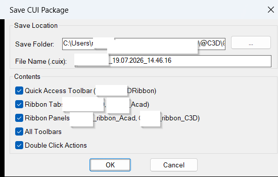
SaveCUIX is an AutoCAD and Civil 3D customization utility for creating a controlled CUIX export from the active CIVIL.cuix file. The command finds CIVIL.cuix on the AutoCAD support path, opens a DCL dialog, lets the user choose the output folder and file name, and then builds a filtered CUIX package using a hidden PowerShell workflow.
The tool is designed for CAD administrators who need to package selected ribbon customizations without manually editing the CUI editor. It can preserve the Quick Access Toolbar target [username]_C3DRibbon, ribbon tabs [username]_C3D and [username]_Acad, ribbon panels [username]_ribbon_Acad and [username]_ribbon_C3D, all toolbars, and all double-click actions depending on the dialog toggles selected by the user.
Internally, SaveCUIX treats the CUIX file as a compressed package, extracts it to a temporary workspace, edits XML-based CUI files such as RibbonRoot.cui, QuickAccessToolbarRoot.cui, ToolbarRoot.cui, and DoubleClickRoot.cui, then repacks the result into a new .cuix file. The source CIVIL.cuix is used as the input package, while the selected destination file becomes the generated filtered output.
ToolPaletteExporter
ToolPaletteExporter scans AutoCAD Tool Palette locations, discovers XTP palette files, lets the user filter and select palettes from a DCL dialog, and exports each selected palette into a structured archive. It reads the ToolPalettePath from AutoCAD preferences, searches saved custom XTP folders, scans OneDrive variants under USERPROFILE, checks Documents, and resolves source paths that contain user profile or OneDrive placeholders.
The exporter parses each selected XTP file for SourceFile entries, resolves those paths, deduplicates referenced files, copies found source files into extension-based archive folders, includes the palette XTP file, includes the matching palette image folder when present, and writes a Files_not_found.csv report. When missing files are detected, it opens a results dialog with full missing paths and a Copy to Clipboard option.
RibbonManagerPlugin
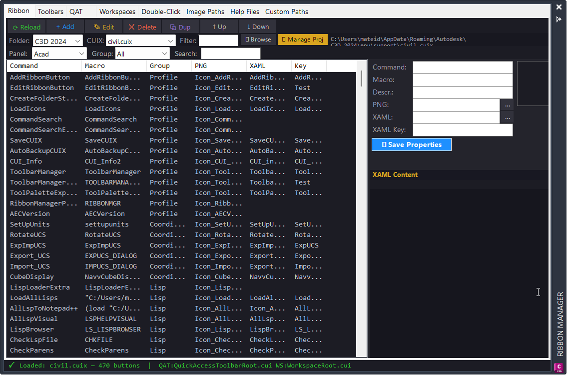
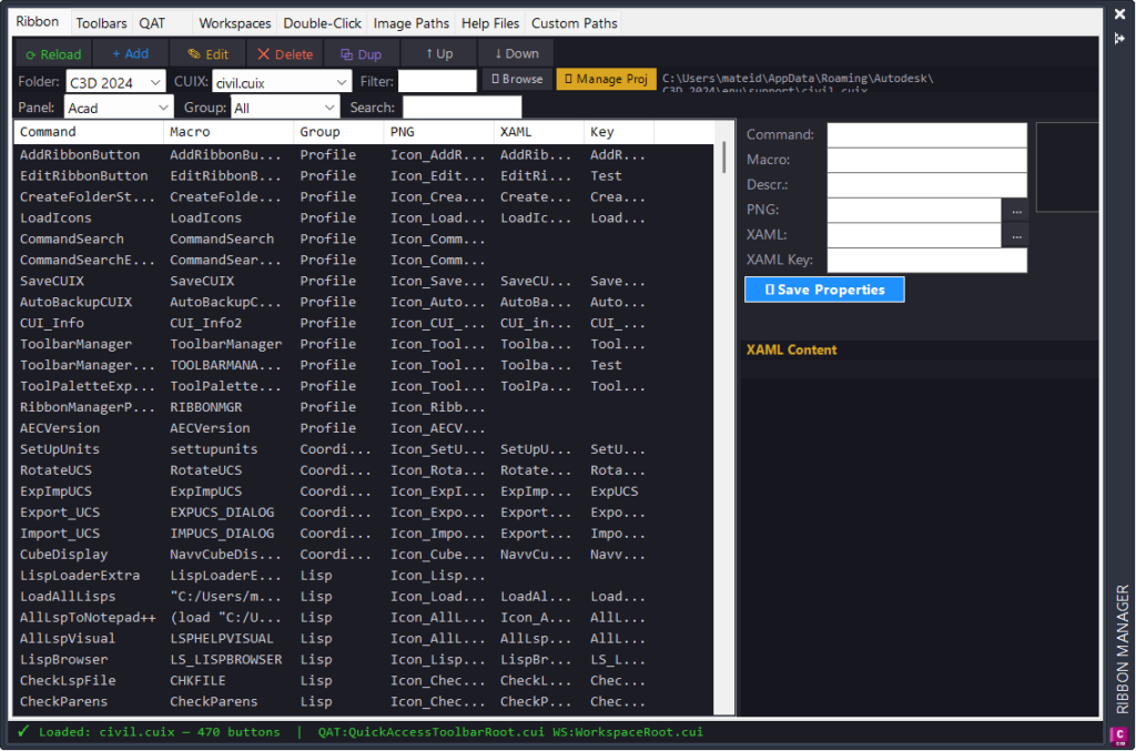
RibbonManagerPlugin is a C# AutoCAD and Civil 3D plugin that manages ribbon commands inside loaded CUIX files through a visual PaletteSet interface. The plugin opens with the RIBBONMGR command and provides a centralized workspace for reviewing ribbon panels, command buttons, macros, icons, XAML help links, Quick Access Toolbar entries, workspaces, double-click actions, image paths, help files, and custom paths.
The project targets .NET Framework 4.8 x64 and builds as RibbonManagerPlugin.dll. It reads CUIX packages as ZIP archives, edits RibbonRoot.cui and MenuGroup.cui XML directly, saves changes back into the live CUIX file, creates a .bak backup, and calls Application.ReloadAllMenus so AutoCAD and Civil 3D reload the updated ribbon configuration.
The tool is designed for CAD managers, Civil 3D power users, ribbon customization workflows, and production environments with many custom [username]_ribbon_* panels, icons, macros, and command help files.
LoadIcons
LoadIcons is an AutoCAD and Civil 3D ribbon icon deployment utility written in AutoLISP. It automates the process of collecting icon files from a structured Help_File library and copying them into the Civil 3D support Icons directory used by AutoCAD ribbon buttons.
The tool recursively scans the configured source folder for files matching
Icon_*.png, skips folders namedss, overwrites matching destination files, and reports the total number of copied icons. After copying, it searches forCIVIL.cuix, unloads and reloads the CUIX so the AutoCAD and Civil 3D ribbon interface can refresh the updated images.This workflow is useful for CAD administrators, Civil 3D customization workflows, ribbon button maintenance, icon library synchronization, and Help_File based toolbar or ribbon systems.
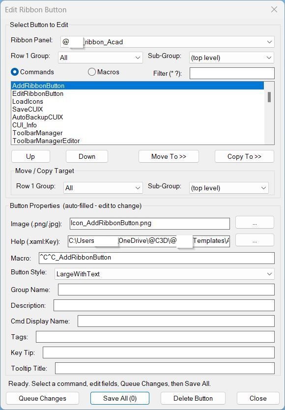
EditRibbonButton
EditRibbonButton is an AutoLISP and PowerShell based AutoCAD ribbon editing utility designed for CAD managers and Civil 3D production environments that maintain many custom ribbon commands in CUIX files.
The tool scans the AutoCAD support directory for the CUIX file containing
[username]_ribbon_*ribbon panels, reads ribbon panel structure and menu macro data, and displays editable command information in a practical DCL interface.Users can select a ribbon panel, group, subgroup, command, or macro, then update the button image, extended XAML help file and key, macro string, button style, group name, description, command display name, tags, key tip, and tooltip title.
Version 4.5 improves the XAML browse workflow by rebinding all dialog actions after the help-file picker reopens the main dialog. This keeps Queue Changes working after XAML browsing and uses the selected command’s existing
ExtendedHelpFileas the default browse path.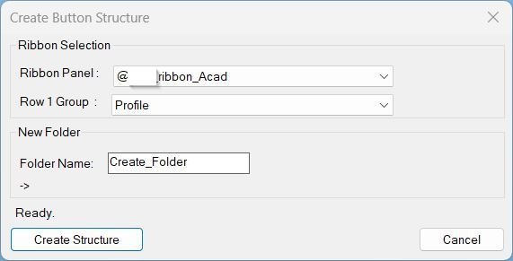
CreateFolderStructure
CreateFolderStructure.lsp is a production helper for AutoCAD and Civil 3D ribbon customization workflows. It creates the standard Help_File folder layout used for new ribbon button documentation and support files.
The tool reads CIVIL.cuix from the AutoCAD search path, extracts ribbon panels named [username]_ribbon_*, finds Row 1 ribbon groups, and maps the selected ribbon and group to the correct Help_File destination. For [username]_ribbon_Acad it writes directly under the main Help_File folder. For [username]_ribbon_XXX it creates the structure under the matching discipline subfolder.
After the user selects the ribbon panel, group, and new folder name, the script creates the target command folder, adds a blank Icon_Name.png file, adds a blank Name.lsp file, creates a Name.xaml file from the configured template, replaces the template x:Key with TName, and builds screenshot and compiled-code subfolder structures for ss_00 through ss_03 and vlx_fas_00 through vlx_fas_03.
The workflow uses temporary DCL dialogs, PowerShell file operations, a VBS launcher, persisted history in the TEMP folder, and a diagnostic command for support and troubleshooting.
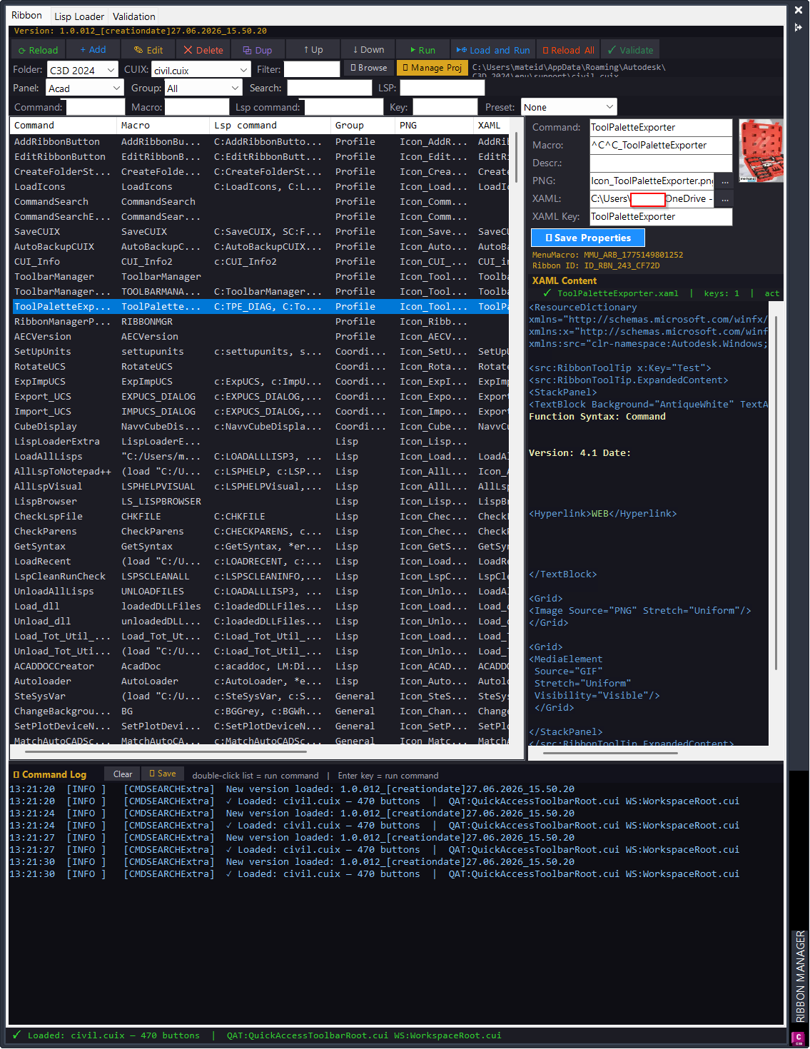
CommandSearchExtra
CMDSEARCHExtra is a productivity project for AutoCAD and Civil 3D built as a .NET Framework 4.8 x64 plugin. It combines a modeless Ribbon command search palette with a dedicated Lisp Loader, a CUIX inspection engine, validation tools, metadata auditing, and documentation export.
The project assembly is CMDSEARCHExtra.dll and the uploaded source declares AssemblyVersion 1.0.012. The main command is CMDSEARCHExtra, which opens a command-management palette for loaded CUIX command data. The palette can browse Ribbon commands, show macros, resolve linked images and XAML help keys, filter by command, macro, LSP command, group, source key, file size, created date, and modified date, and run commands directly from the grid.
The Lisp Loader side scans AutoCAD and Civil 3D support folders for LSP, VLX, FAS, and DLL files. It extracts AutoLISP command definitions, shows category/menu/command metadata, loads checked or selected files, tracks OK, failed, missing, and skipped results, records live logs, and opens detailed reports.
The project also includes validation logic for duplicate Ribbon commands, duplicate XAML keys, duplicate LSP commands, missing macros, missing files, macro-to-defun consistency, hard-coded paths, dependency warnings, and large-file checks. Validation data can be exported to CSV or HTML, and the documentation generator can create an HTML command catalog.
CUIX write operations use a timestamped backup workflow before modifying the live CUIX file. This is important because the tool can add, edit, delete, duplicate, move, and repath Ribbon command button data.
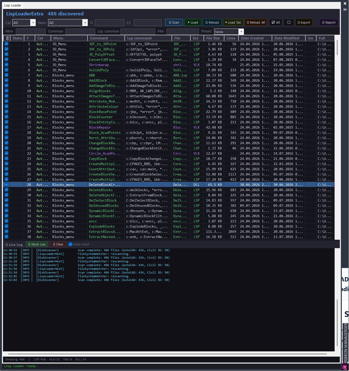
CommandSearch Lisp Loader Only
CommandSearch Lisp Loader Only is a C# AutoCAD and Civil 3D plugin built for CAD managers and production users who maintain large ribbon, CUIX, LISP, VLX, FAS, and DLL command libraries.
The project combines a Command Search palette with a dedicated Lisp Loader workflow. It reads ribbon button data from selected CUIX files, displays command names, macros, panels, groups, image paths, XAML help references, and LSP command links, then helps validate and maintain the command library from one interface.
The Lisp Loader scans configured Help_File folders, detects loadable AutoCAD support files, extracts AutoLISP command defuns, displays file metadata, loads checked or selected tools, supports reload-all workflows, and records results in a live log and report window.
The uploaded project is a Visual Studio C# project targeting .NET Framework 4.8 and x64. It depends on local AutoCAD and Civil 3D references through the AutoCAD_Civil3D_refferences.props import, so a full build requires that local reference environment.
AutoBackupCUIX
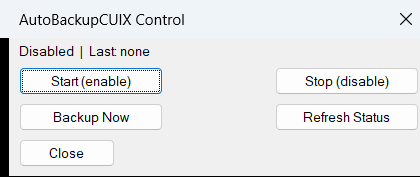
AutoBackupCUIX is a practical Civil 3D CUIX backup automation tool designed to protect customized ribbon and toolbar configuration data. The routine searches for CIVIL.cuix using AutoCAD findfile, creates a timestamped backup named [username]C3D_dd.mm.yyyy_hh.mm.ss.cuix, and stores it in the configured menu folder.
The automatic schedule is controlled by a vlr-command-reactor on :vlr-commandEnded, which makes the workflow compatible with Civil 3D versions where vlr-idle-reactor is not available. After the configured time has passed, the next completed AutoCAD command can trigger the backup once per day.
The backup core launches a hidden PowerShell process through a temporary VBS script. PowerShell extracts the CUIX archive, edits RibbonRoot.cui, keeps only the configured ribbon panel sources and tab sources, rebuilds the CUIX package, and writes a done file so AutoLISP can report success, failure, or timeout.
AddRibbonButton
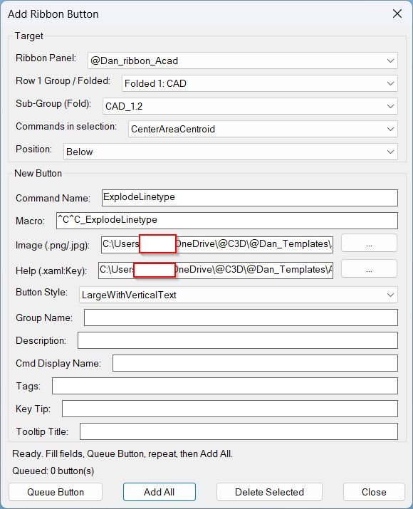
AddRibbonButton is an AutoCAD ribbon customization utility written in AutoLISP. It reads the CIVIL.cuix ribbon structure, displays @Dan_ribbon_* panels and groups in a DCL dialog, and lets the user create new ribbon command buttons with image, help XAML, macro, group, description, display name, tags, key tip, tooltip title, and button style settings. The tool can queue multiple buttons and patch the CUIX file in one operation using a temporary PowerShell workflow.
AECVersionPlugin
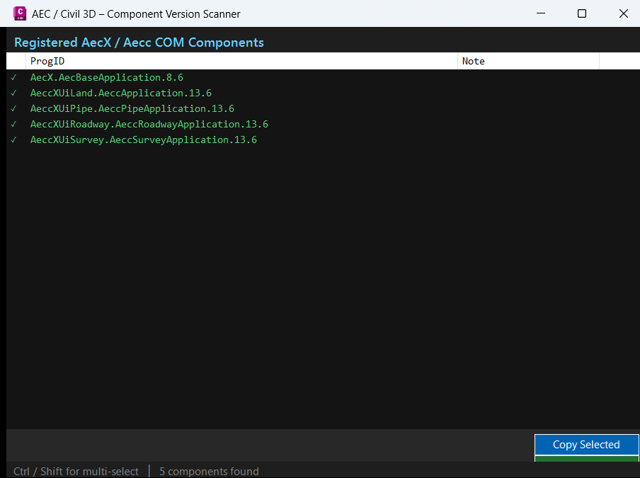
AECVersionPlugin is a Visual Studio C# project setup for an AutoCAD and Civil 3D .NET plugin that is intended to expose the
AECVERSIONcommand after loadingAECVersionPlugin.dllwithNETLOAD.The project targets .NET Framework 4.8, builds as a class library, uses x64 platform settings, and enables Windows Forms support for dialog-based AutoCAD plugin interfaces. It references the core AutoCAD managed assemblies required for command registration, database access, and application/document interaction.
This makes the project suitable for CAD managers, Civil 3D administrators, BIM/CAD support teams, and AutoCAD plugin developers who need a structured project file for building an AEC version diagnostic utility.
ToolbarManager_vs.01
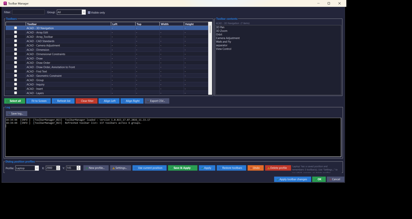
📘 ToolbarManager scans the active AutoCAD or Civil 3D session, reads every available toolbar from every AutoCAD menu group, and presents the result in a filterable grid. The user can search toolbars, filter by menu group, show only visible toolbars, inspect toolbar commands, and apply visibility changes from one central panel.
🔍 The program is designed for CAD users who work with many floating AutoCAD toolbars, custom CUI toolbars, Civil 3D workspaces, and multi-monitor layouts. It records each toolbar label, group, visibility state, screen position, width, height, and toolbar contents where AutoCAD exposes that information through the COM API.
📌 A key purpose of the tool is toolbar profile management. Users can save named profiles such as office monitor, laptop, docking station, or project-specific layouts, then restore the dialog position and saved floating toolbar set later. This makes it easier to move between Civil 3D workstations, screen resolutions, remote sessions, and multiple monitor arrangements.
🧠 The project includes a monitor-aware fix through
ScreenHelper.cs. Instead of relying on AutoCADSCREENSIZE, it uses the AutoCAD main window handle and Windows screen detection to determine the correct monitor. This improves Fit to Screen behavior when Civil 3D is not on the primary display.📊 The settings dialog provides advanced profile editing, toolbar ordering, align tools, gap control, distribution, CSV import/export, clipboard round-trip support, and right-click context menus. This makes the plugin useful for AutoCAD toolbar organization, Civil 3D UI standardization, workspace recovery, and CAD production setup automation.
ImportBlock
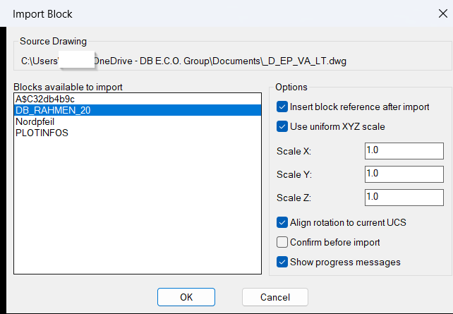
📘 ImportBlock is designed for AutoCAD and Civil 3D users who need to reuse block definitions from another drawing without opening several manual dialogs or copying geometry by hand.
The user starts the command, chooses a source drawing file, selects a block from a generated list, and decides whether the block definition should only be imported or also inserted immediately into the active drawing.
The routine reads external drawing content throughObjectDBXusingvla-getinterfaceobjectandvla-open, then deep-copies the chosen block definition into the current drawing block table withcopyobjects.
The DCL window includes practical options for insert after import, uniform scale, separate X/Y/Z scale, current UCS rotation alignment, confirmation before import, and progress messages.
When insertion is enabled, the user picks an insertion point and the routine callsvla-insertblockin the current drawing space. The picked point is converted from UCS to WCS usingtrans, which helps the block land correctly in custom AutoCAD UCS workflows.
For CAD standards and reusable block libraries, this tool improves AutoCAD block management, Civil 3D production drawing setup, DWG content reuse, block import automation, and external drawing block extraction.
InsertBlockFilterScale
📘 InsertBlockFilterScale scans the active drawing block table and lists available block definitions that can be inserted into the drawing.
The tool excludes anonymous block names, xref block definitions, and externally referenced block names containing a pipe character, so the user works mainly with normal local block definitions.
The user can type a block-name filter, select one or multiple block names, preview the selected block definition, define an XY scale, define a rotation angle in degrees, and insert the selected blocks by picking insertion points in the drawing.
The block preview is drawn directly in the DCL image tile using simplified vector geometry from the block definition, with layer color resolution for ByLayer entities and a visible fallback for ByBlock entities.
When the user inserts a block, the routine transforms the picked UCS point into WCS, adjusts the rotation by the current UCS direction, and inserts the block into model space withvla-insertblock.
This makes the utility useful for AutoCAD block libraries, Civil 3D production drawings, title block drafting, detail insertion, standard symbol placement, CAD cleanup, and block management workflows.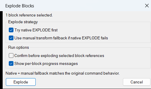
ExplodeBlocks
📘 ExplodeBlocks is designed for CAD drawings where normal block explosion is blocked by settings or complicated by non-uniform scale.
The user runsExplodeBlocks, selects one or more block references, and the LISP attempts to explode each selected object.
For standard cases, the routine temporarily enables the block definitionExplodableproperty, runs the native AutoCAD._EXPLODEcommand, then restores the original explode setting.
If the native explode attempt fails, the routine uses a manual transformation workflow: it reads the block reference insertion point, scale factors, and rotation, builds a transformation matrix, copies entities from the block definition, applies the full block transform, and deletes the original block reference.
This makes the tool useful for AutoCAD DWG cleanup, Civil 3D plan production, external reference preparation, block editing, drawing standardization, and converting protected or non-uniformly scaled blocks into direct geometry.
The routine is especially useful when users need editable geometry from block references that cannot be exploded cleanly with the standard AutoCAD command.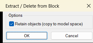
DeleteObjectFromBlock
📘 This AutoLISP program provides a compact block cleanup workflow for AutoCAD users who need to extract or remove individual nested objects from inside a block reference without opening the Block Editor manually.
The user startsExtractFromBlockorDeleteObjectFromBlock, chooses whether to retain objects by copying them to model space, and then picks nested geometry inside block references withnentselp.
When Retain objects is enabled, the selected nested object is copied into model space, transformed with the nested selection matrix, assigned to a cleaned local layer name, and then deleted from the source block definition.
When Retain objects is disabled, the selected nested object is deleted only from the block definition without creating a model space copy.
This tool is useful for AutoCAD block cleanup, nested object extraction, block definition editing, symbol repair, DWG maintenance, drawing simplification, and CAD production cleanup.
Important: the program edits the source block definition, so all block references that use the same definition may change after the selected nested object is removed.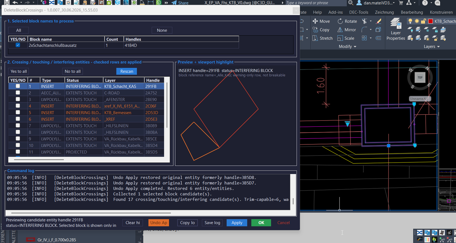
DeleteBlockCrossings
📘 DeleteBlockCrossings is a productivity tool for AutoCAD and Civil 3D users who need to clean up lines, polylines, splines, arcs, and other curve geometry where it crosses selected block references. The user selects one or more blocks in the drawing, runs
DELETEBLOCKCROSSINGS,DBC, orABBS, and the plugin opens a modeless C# control panel.🔍 The program reads the selected block references, resolves their effective block names, builds block frames from the block definition and block transform, then scans the same owner drawing space for candidate curves and nearby block references. It classifies the detected geometry as CROSSING, TOUCHING, CROSSING – CHECK, PROJECTED, EXTENTS TOUCH, or INTERFERING BLOCK.
📐 Rows marked as CROSSING are trim-capable when the plugin can calculate a safe two-point break pair. These rows can be checked and processed. Warning-only rows remain visible for CAD review, but their checkboxes are disabled because the code does not have a safe automatic trim operation for those cases.
🧠 The plugin uses AutoCAD database transactions, block frame geometry, intersection checks, sampled curve diagnostics, preview geometry, and split-curve processing to remove the part of each crossing curve that falls inside the selected block frame. This helps users automate repetitive block crossing cleanup while still showing diagnostics before modifying the drawing.
📝 The modeless interface includes selected block groups, crossing and touching rows, preview and viewport highlight, command log, apply, undo apply, copy log, save log, clear highlight, OK, and Cancel actions. Settings are stored under
%APPDATA%\DeleteBlockCrossings\DeleteBlockCrossings.cfg, and diagnostic logs can be saved as text files.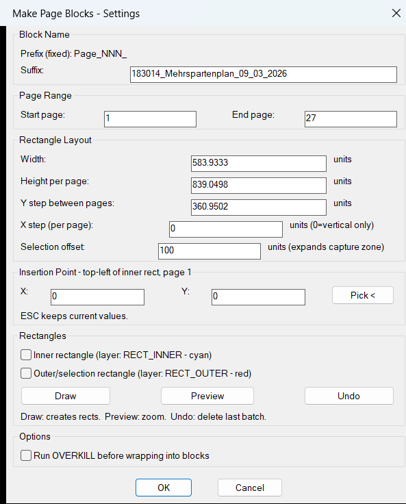
CreateMultipleRectangleBlocks
📘 CreateMultipleRectangleBlocks automates a repetitive AutoCAD and Civil 3D drafting workflow where several page areas must be framed, previewed, collected, and converted into separate block definitions.
The user runs
CreateMultipleRectangleBlocks, enters a page range such as page 1 to page 27, defines a suffix for the generated block names, and sets the rectangular page dimensions. The tool can draw inner rectangles onRECT_INNERand outer selection rectangles onRECT_OUTER, preview the drawn area by zooming to the calculated bounding box, and undo the last rectangle batch with AutoCADUNDO BACK.After the user accepts the dialog, the routine calculates every page origin from the top-left insertion point, page height, Y step, and optional X step. It then scans the active drawing entities, assigns objects to page zones based on their Y coordinate, and creates page block definitions named with the format
Page_NNN_suffix. For every non-empty page zone, the routine creates a block definition at the page origin, copies matching entities into the block, inserts the block reference, and deletes the original source entities that were wrapped into the block.This is useful for AutoCAD production drawings, Civil 3D sheet preparation, plan extraction, page packaging, drawing cleanup, and workflows where repeated rectangular areas need to become reusable block references.
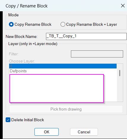
CopyBlock_vs.01
📘 CopyBlockChangeLayer is designed for AutoCAD users who need to duplicate a block reference and turn the duplicated reference into a new renamed block definition.
The user selects one block reference in the drawing, enters a new block name, chooses whether the operation should only rename the copied block or also apply a layer, and then confirms the dialog.
The program reads the selected block reference, determines its effective block name where supported, proposes a unique default name such asBlockName_1, validates the new name withsnvalid, and prevents overwriting an existing block definition.
Internally, the routine usesObjectDBXandvla-CopyObjectsto copy the original block definition into a temporary database, rename it, and copy the renamed definition back into the active drawing.
After the renamed block definition is created, the selected block reference is copied withvla-Copy, the copied reference is retargeted to the new definition withvlax-put-property, and the original block reference can be deleted automatically through the defaultDelete Initial Blockoption.
In the Copy Rename Block + Layer mode, the user can filter the drawing layer list, choose a target layer, or pick an object from the drawing to read its layer. The copied block reference is then placed on that layer, and the new block definition contents can be forced to the same layer with color, linetype, and lineweight reset to ByLayer.
This is useful for AutoCAD block management, DWG cleanup, layer standardization, construction detail variants, drawing production, block renaming, and CAD library workflows where a copied block must become an independent block definition.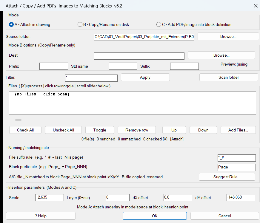
AttachImagesToBlocks
📘 AttachImagesToBlocks is a production-focused AutoLISP and DCL tool for AutoCAD and Civil 3D users who need to connect external PDF sheets or raster image files with matching block references in the active DWG.
🔍 The user opens one shared dialog, selects a source folder, scans PDF and image files, defines the file-page extraction rule, defines the block-name prefix rule, and lets the matching engine pair each file with a drawing block using the extracted page number.
📐 The routine supports three practical workflows. In attach mode, matched files are placed in model space at the corresponding block insertion point with configurable scale, layer, horizontal offset, and vertical offset. In copy and rename mode, matching files are copied to a destination folder and renamed from the block name or from a user-defined pattern. In add-to-block-definition mode, the file is attached temporarily, transformed from model space into the block definition coordinate system, copied into the block table record, and the temporary model space entity is deleted.
🧠 The dialog includes scan, folder browse, destination folder browse, select all, select none, toggle, remove, move up, move down, add external files, rule suggestion, help, filter, horizontal list scrolling, rename preview, and summary counters. This makes it useful for automated DWG underlay placement, PDF sheet indexing, raster image attachment, block definition enrichment, and Civil 3D plan production workflows.
🔒 Settings are saved beside the drawing in
AIB_settings.cfg, so scale, offsets, layer, folder paths, matching rules, filters, and rename pattern values can be reused during the next command run.Convert3DFaceToPolyline
📘 Convert3DFaceToPolyline is an AutoCAD and Civil 3D utility description for an AutoLISP workflow that converts selected
3D Faceentities into closedPolylinegeometry.🔍 The user runs
Convert3DFaceToPolyline, selects 3D face objects in the drawing, and the program iterates through the selection set. For each selected face, the routine extracts the four vertex coordinates from the entity data and uses those points to draw a closed polyline outline.📐 This workflow is useful when DWG files contain face-based geometry that needs to be reviewed, traced, simplified, exported, or managed as standard AutoCAD polyline boundaries. Civil 3D users can use the converted polyline outlines for cleanup, plan production, geometry checking, and preparation before other drafting or modeling tasks.
🧠 The provided file is a WPF or AutoCAD ribbon tooltip resource named
Convert3DFaceToPolyline.xaml. It documents the command behavior and user workflow; the actual AutoLISP implementation must be loaded separately for the command to run.3DF_to_3DPoly
📘 3DF_to_3DPoly is a focused AutoLISP conversion tool for AutoCAD and Civil 3D users who need to convert
3DFACEgeometry into normal closed3D Polylineobjects.🔍 The user runs
3df2pl, selects the required 3DFACE entities in the drawing, and the program reads the four vertex coordinates stored in the entity definition. Each face is then recreated as a closed 3D polyline using the AutoCAD._3dpolycommand.📐 Because the routine uses the original 3D face vertex points, the resulting 3D polylines keep the Z elevations from the source faces. This is useful for Civil 3D cleanup, survey geometry processing, 3D drafting, terrain boundary preparation, legacy DWG conversion, and CAD quality-control workflows.
🧠 The LISP includes a Civil 3D compatibility header, a guarded
vl-load-compattern, local error handling, and system variable restoration forCMDECHOandOSMODE. The workflow is intentionally simple: select faces, convert them, and continue working with editable 3D polyline geometry.BookmarkEntities
📘 BMEntityPos is an AutoCAD and Civil 3D AutoLISP utility that creates a practical bookmark manager for drawing entities.
The user runsBMEntityPos, opens a DCL dialog, selects drawing objects, and stores each object as a bookmark with label, bounding-box start point, bounding-box end point, color information, object handle, entity type, and remark text.
The tool is useful for CAD review, model checking, object tracking, issue navigation, drawing cleanup, and returning quickly to important DWG locations without manually searching through the drawing.
The program supports common AutoCAD entity types such asTEXT,MTEXT,LINE,LWPOLYLINE,POLYLINE,CIRCLE,SPLINE, andINSERTblock references.
It uses synchronized list boxes to show element data, coordinates, color, and remarks, while group filtering allows the user to view Text, Lines, Polylines, Circles, Splines, Blocks, or all saved bookmarks.
For reliable navigation, the routine attempts to resolve the saved entity handle withhandentand refresh the bounding box before zooming. If the entity no longer exists, it falls back to stored coordinates.
Important limitation: this AutoLISP program does not edit Civil 3DProfileView,SectionView,Alignment, bands, labels, corridors, surfaces, or Civil 3D styles. Its real purpose is AutoCAD entity bookmarking, DCL-based bookmark management, saved view navigation, remark tracking, and list-file persistence.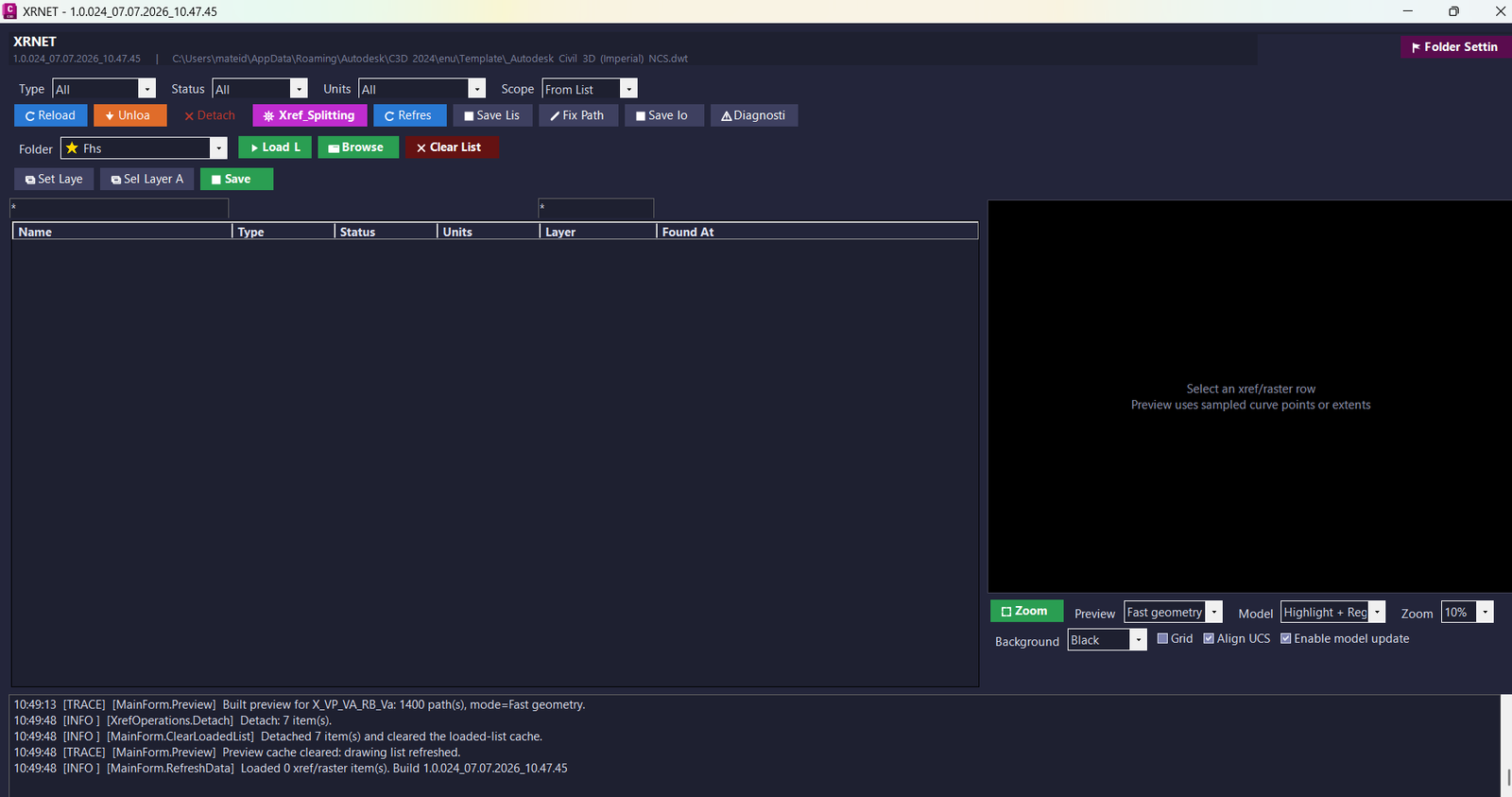
XrNet
📘 XRNET scans the active DWG and collects detected DWG xrefs and raster image references.
The program displays the reference name, xref type, load status, drawing units, layer, and source file path in a practical grid for AutoCAD and Civil 3D production drawings.
CAD users can select one or multiple external references and run xref management actions without manually switching between several AutoCAD dialogs.
The plugin supports reload, unload, detach, path validation, path repair, layer assignment, list export, preview, and diagnostic workflows.
TheXRSPLITworkflow loads xref list TXT files, imports current drawing references, validates paths, scans folders, merges lists, exports rows, generates layers, creates abbreviations, and applies selected entries back to the active DWG.
Important limitation: this plugin does not edit Civil 3DProfileView,SectionView,Alignment, bands, labels, or Civil 3D styles. Its real purpose is AutoCAD and Civil 3D xref management, raster reference management, DWG dependency cleanup, preview, export, diagnostics, and file path validation.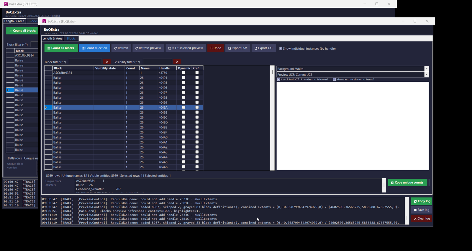
BoQExtra
📐 BoQExtra is designed for AutoCAD and Civil 3D projects where users need reliable quantity takeoff, geometry measurement, block counting, layer control, drawing validation, and Excel-ready formulas without repeating manual drafting and spreadsheet work. The tool focuses on model-space objects and block references, making it practical for construction drawings, utility plans, cable routes, drainage details, KTB layouts, KAS symbols, Civil 3D production sheets, and infrastructure BoQ workflows.
📊 In the Length and Area tab, the user can select supported AutoCAD geometry by layer, by screen selection, or directly from the table. The plugin calculates object type, layer, handle, length, area, closed polyline state, per-entity minimum length, per-entity maximum length, and repeated vertical dimension values. It supports common drawing objects such as lines, 2D polylines, lightweight polylines, 3D polylines, arcs, circles, splines, and ellipses.
🧩 In the Blocks tab, the user can count all block references or only selected block references. The plugin displays block name, visibility state, count, unique block-name counters, object handle, dynamic block status, and xref status. A dedicated bottom counter summarizes each unique effective block name, so users can immediately see how many instances of manhole blocks, KAS blocks, connection blocks, cable-route blocks, or custom CAD library blocks exist in the filtered table.
📝 The plugin generates clipboard-ready formulas and drawing-ready MTEXT output. It can copy raw values, detailed expressions, CEILING formulas, profile-based formulas, raw length formulas, raw area formulas, and field-based formulas linked to object handles where possible. This improves BoQ traceability because the user can keep both the result and the calculation logic instead of manually typing static numbers.
🔍 The integrated preview system shows selected objects and surrounding context geometry, supports white background display, UCS-oriented preview rotation, mouse-wheel zoom, pan, fit all, fit selected, and model-space zoom actions. Selection in the table can also synchronize with AutoCAD model space selection, which helps users visually confirm exactly which drawing objects are being measured or counted.
🧠 The plugin is useful inside Civil 3D drawings that may also contain Alignment objects, ProfileView objects, SectionView objects, labels, bands, styles, corridors, pipe networks, surfaces, parcels, and production annotations. BoQExtra does not directly modify ProfileView, SectionView, Alignment, labels, bands, or styles. Its role is to measure and manage model-space entities, layers, block references, field text, preview data, and export tables that support Civil 3D quantity extraction and drawing quality control.
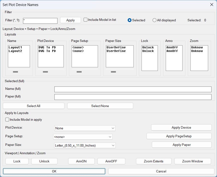
SetPlotDeviceNames
🖨️ SetPlotDeviceNames is an SEO-friendly AutoCAD layout plotting utility for managing plot device names, page setups, canonical media names, and paper sizes from one DCL interface.
📊 The dialog shows synchronized layout columns for Name, Plot Device, Page Setup, Paper Size, Lock, Anno, and Zoom, with compact column widths and horizontal sliders for long values.
🔍 Users can filter layout names using wildcard patterns, include or exclude Model in the list/apply scope, and choose between selected rows or all displayed rows.
📐 The tool can batch-apply plot devices, page setups, and paper sizes to selected layouts, while also managing paper-space viewport lock state and annotation visibility.
🧭 Zoom tools let the user apply Zoom Extents or pick a Zoom Window for layout viewports, with zoom state persisted through a named-object dictionary record.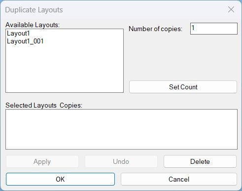
DuplicateLayouts
📄 DuplicateLayouts is an SEO-friendly AutoCAD layout duplication tool designed for drawing sheets, paper-space tabs, plotting workflows, and Civil 3D sheet production.
🔁 The routine builds a temporary DCL dialog named Duplicate Layouts with an Available Layouts list, Number of copies input, Selected Layouts and Copies summary, Apply, Undo, Delete, OK, and Cancel controls.
🧠 Each selected source layout can receive its own copy count. The tool generates unique names by appending three-digit suffixes such as Layout_001, Layout_002, and Layout_003.
🧩 Layout duplication is performed through the AutoCAD -LAYOUT Copy workflow, with fallback command keywords to improve compatibility across localized or command-option variations.
🗑️ The Delete button can remove a selected entry from the summary list or delete an actual layout tab from the drawing when a layout is selected in the Available Layouts list.
📌 This is useful for batch sheet creation, repeating plotting layouts, Civil 3D plan set preparation, viewport-based drawing sheets, and production drawings where many similar tabs must be generated quickly.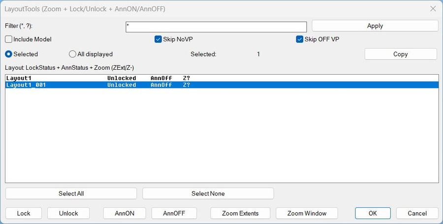
LayoutTools
🧰 LayoutTools is an SEO-friendly AutoCAD layout and viewport management utility for Civil 3D sheet production and paper-space cleanup.
📑 The routine creates a DCL dialog titled LayoutTools with filter, Include Model, Skip NoVP, Skip OFF VP, Selected versus All displayed scope, layout status table, Select All, Select None, Copy, Lock, Unlock, AnnON, AnnOFF, Zoom Extents, and Zoom Window.
🔒 Lock and Unlock change DisplayLocked on viewports found in the target layouts, helping protect viewport scales and sheet views from accidental edits.
👁️ AnnON and AnnOFF set ANNOALLVISIBLE across selected or displayed layout tabs, allowing faster annotation visibility control during checking and plotting.
🔍 Zoom Extents and Zoom Window run after the dialog closes for command-safety, then apply the chosen view action across the target layouts.
💾 The tool stores zoom status in a Named Object Dictionary XRECORD so the list can show ZExt, Z-, or Z? status for tracked layouts.
📌 This is useful for viewport locking, layout review, sheet cleanup, annotation checks, batch zooming, plot preparation, and Civil 3D plan sheet QA/QC.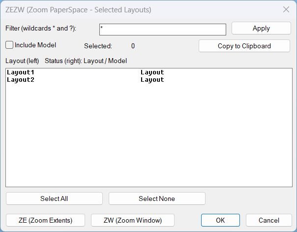
Zoom Extend Window
User workflow- Run ZEZW to open the layout selection dialog.
- Use the filter box with wildcards * and ? to narrow the layout list.
- Optionally toggle Include Model to show or hide MODEL in the list.
- Multi-select layouts in the list (fixed width display shows layout name and status).
- Click ZE (Zoom Extents) to zoom extents on each selected layout in Paper Space.
- Click ZW (Zoom Window) to pick two corners once, then apply the same zoom window to each selected layout in Paper Space.
- If selection is empty, the program prompts the user to select one or more layouts before running zoom.
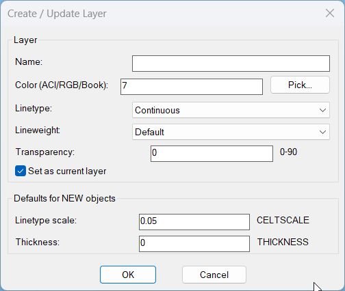
LayerCreation
🧱 LayerCreation is an SEO-friendly AutoCAD layer creation and layer-standard utility for building or updating drawing layers with consistent properties.
🎨 The routine supports standard ACI colors, RGB true-color values, and color book selections, making it more flexible than a simple layer-name macro.
📐 It lets the user define linetype, lineweight, transparency, CELTSCALE, CETRANSPARENCY, THICKNESS, and whether the new layer should become current.
🧠 The dialog path uses dynamically generated DCL, while NEWLAYERCLI provides a command-line fallback if DCL is not healthy in the AutoCAD session.
📌 This is useful for CAD standards, Civil 3D layer setup, project templates, repeated layer creation, and controlled drawing initialization.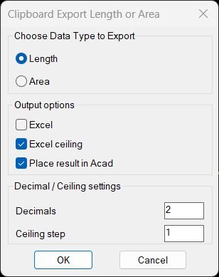
TotalLengthAreaDetailed
📏 TotalLengthAreaDetailed is a dialog-driven AutoCAD and Civil 3D measurement utility for quantity takeoff, CAD calculation review, and production documentation. It calculates either total length or total area from supported drawing entities and builds a detailed additive expression such as 1.25+3.50+2.00.
📋 The tool copies the final expression to the Windows clipboard as plain text, an Excel-ready formula, or a CEILING formula. This makes it practical for BoQ workflows, quantity checking, Excel reporting, cable route measurement, layer-based calculations, and CAD production summaries.
📝 When Place result in Acad is enabled, the routine inserts MTEXT in the current drawing at a user-picked point. The insertion is UCS-aware and the result can be created as dynamic AutoCAD field text where supported, so selected object values can remain linked to the source entities.
🏷️ Version 02 behavior places the result MTEXT on the first selected entity layer. The Acad_Length or Acad_Area layer result label also uses the first selected layer name, making the output easier to audit directly inside the drawing.
🧮 Area mode includes optional Profile_002 profile presets such as Profile_002, Profile_003, Profile_004, and Profile_005. These presets convert a summed area expression into a profile-based expression by dividing by the selected internal width.
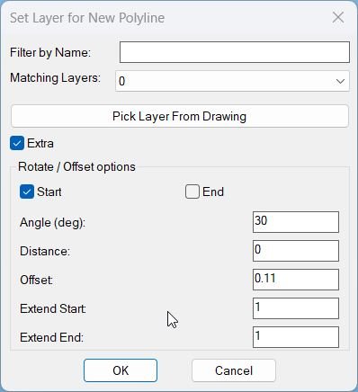
CopySelection_vs.01
• Polyline and points: After you choose an LWPOLYLINE, the routine asks for two points along it, snaps them to the closest points on the curve, and ensures they are not identical before continuing. • Segment extraction: Uses curve parameters at the two picked locations to slice the source polyline between those parameters, reconstructing a new vertex list that represents only the chosen segment (including bulges and widths). • Header cloning: Copies the original polyline’s non vertex DXF data, forces the new polyline onto the chosen target layer, and clears the closed flag so the result is an open segment. • Layer dialog: Builds a temporary DCL file that provides a text filter for layer names, a popup list of matching layers, a button to pick a layer from an existing object, and a toggle to enable or disable Extra transform options. • Layer filtering and pick: Collects all non xref layers, sorts them, filters them dynamically as you type in the filter box, and lets you optionally pick an entity in the drawing to adopt its layer as the target. • Extra options group: When Extra is enabled, the dialog exposes rotation start or end toggle, rotation angle, perpendicular distance, offset style presets, numeric offset, offset copy count, and numeric extension at start and end. • Extension at ends: The extend-ends helper extends the first and last segments of the new polyline by independent distances extS and extE along their segment directions, updating coordinates through COM. • Rotation and distance: Computes a unit direction from the first pick to the second, then rotates the new polyline around the chosen base point (start or end) by the given angle, and moves it perpendicular to that direction by the specified distance. • Offset copies: Creates additional parallel copies of the transformed polyline, spaced by the offset distance along the normal direction, up to the specified offset count; the offset value can be auto filled from presets like DN110, KK I to KK IV. • Persistent settings: Stores the last used layer and filter string in environment variables so that the next run of the command remembers which layer and filter you used previously. • Apply and Undo loop: Wraps operations in a global UNDO group, marks the undo stack before each Apply, and supports stepping back one Apply at a time when you press Undo, without closing the dialog. • Finalization logic: If you never used Apply or Undo, pressing OK performs a single geometry creation using current dialog values; if you cancel, all Apply actions in this session are undone before closing the group.3DPolyVertex2Table
📐 The command accepts one AcDb3dPolyline and extracts its complete coordinate array.
📊 A four column table is generated with Point X Y and Z fields.
🔢 The default source configuration labels vertices with numbers while an adjustment variable can switch the internal markup mode to letters.
🎯 Coordinate precision is configured to four decimal places in the current source.
📌 The table is initially created in ModelSpace then copied and pasted interactively at the user selected insertion point.
⭕ Every 3D polyline vertex receives a text marker and a small circle created with current color temporarily set to red.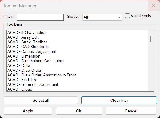
ToolbarManager
• Global session state: Maintains internal lists *tbm-all*, *tbm-view*, the current filter text *tbm-filter*, the visible only toggle *tbm-visonly*, the active group *tbm-group*, and the group list *tbm-groups* so your choices persist while the drawing is open. • Toolbar collection: On each run, the command queries all menu groups from the Acad object, scans each group’s toolbars, and builds a master list of items in the form (label object visible? group). • Label format: Each toolbar label combines the menu group and toolbar name as “Group – ToolbarName” so you can distinguish toolbars with identical names in different groups. • Sorting: The combined toolbar list is sorted first by group name and then by label, giving you a stable and predictable order inside the list box. • Group list building: Extracts the unique group names from the toolbar list and stores them in *tbm-groups*, always inserting “All” as the first option to show toolbars from every group. • DCL dialog creation: Writes a temporary DCL file defining the Toolbar Manager dialog with a filter edit box, group popup, Visible only toggle, multi select list box, and buttons for Select all, Clear filter, Apply, OK, and Cancel. • Initial UI state: The dialog tiles are initialized from the saved global values so your last used filter text, visible only flag, and selected group are restored when you reopen the manager. • View list refresh: Whenever filter, group, or visible only options change, the routine rebuilds *tbm-view* with matching indices from *tbm-all* and repopulates the list box with just those toolbars. • Preselection of visible: After repopulating the list, the code automatically selects entries corresponding to toolbars that are currently visible so you can see your active setup at a glance. • Apply behavior: When you press Apply or OK, the code reads the current list selection and turns on visibility for those toolbars in the current view, setting all other toolbars in the view to hidden. • Visibility update scope: Only the toolbars that match the current filter and group (the current view) are modified; toolbars outside that view keep their existing visibility state. • Filter clearing: The Clear button resets the filter text, updates the filter tile, and refreshes the view so that all toolbars in the chosen group are shown again in the list. • Dialog exit: OK applies the current selection and closes the dialog, Apply updates toolbars but leaves the dialog open, and Cancel closes the dialog without applying any further changes after the last apply.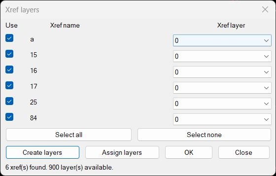
CreatesXrefsLayersAssign_vs.00
The dialog shows one row per found xref: a checkbox to include or skip that xref, the xref name, and a layer popup listing all layers in the drawing. There are buttons to select all or select none, to create suggested layers for the checked xrefs, and to assign the chosen layers to all inserts of the checked xrefs in model space and paper space. The routine also tries to detect the current insert layer of each xref and preselects it in the popup if it exists. A status text at the bottom reports how many xrefs were found and how many layers are available for assignment.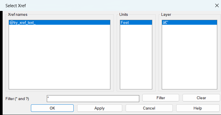
ZoomXref
ZoomXref is an AutoCAD AutoLISP and ActiveX utility that helps users find and zoom to Xrefs quickly from a clean DCL dialog. The tool scans Xref block definitions, displays each Xref name, shows the block table insert units, summarizes the model-space insert layer, and lets the user filter the list live using wildcard patterns such as * and ?. The selected Xref is zoomed by collecting its model-space INSERT references, calculating their bounding box, and calling ActiveX ZoomWindow using the lower-left and upper-right extents.
The command is useful for CAD production drawings that contain many external references, partial references, discipline backgrounds, survey files, layout bases, or coordination models. It provides a faster workflow than manually searching the drawing, opening the external reference palette, or zooming by selection.
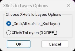
XRefs2Layers
🔗 XRefs2Layers is an AutoCAD AutoLISP utility for organizing external reference inserts by layer.
📂 The tool scans the current drawing for XREF block definitions, ignores names matching *TBLOCK*, finds matching INSERT references, and moves those references to controlled XREF layers.
🧭 The user can run a dialog-based workflow with XRefs2LayersOptions or run direct commands for a specific mode. One mode places every XREF on a shared _XREF layer, while the other mode creates separate 0-XREF_ layers for clearer drawing management.
🛡️ The routine uses ActiveX layer handling, undo marks, locked-layer recovery logic, and a final alert report showing how many XREFs were moved to each target layer.
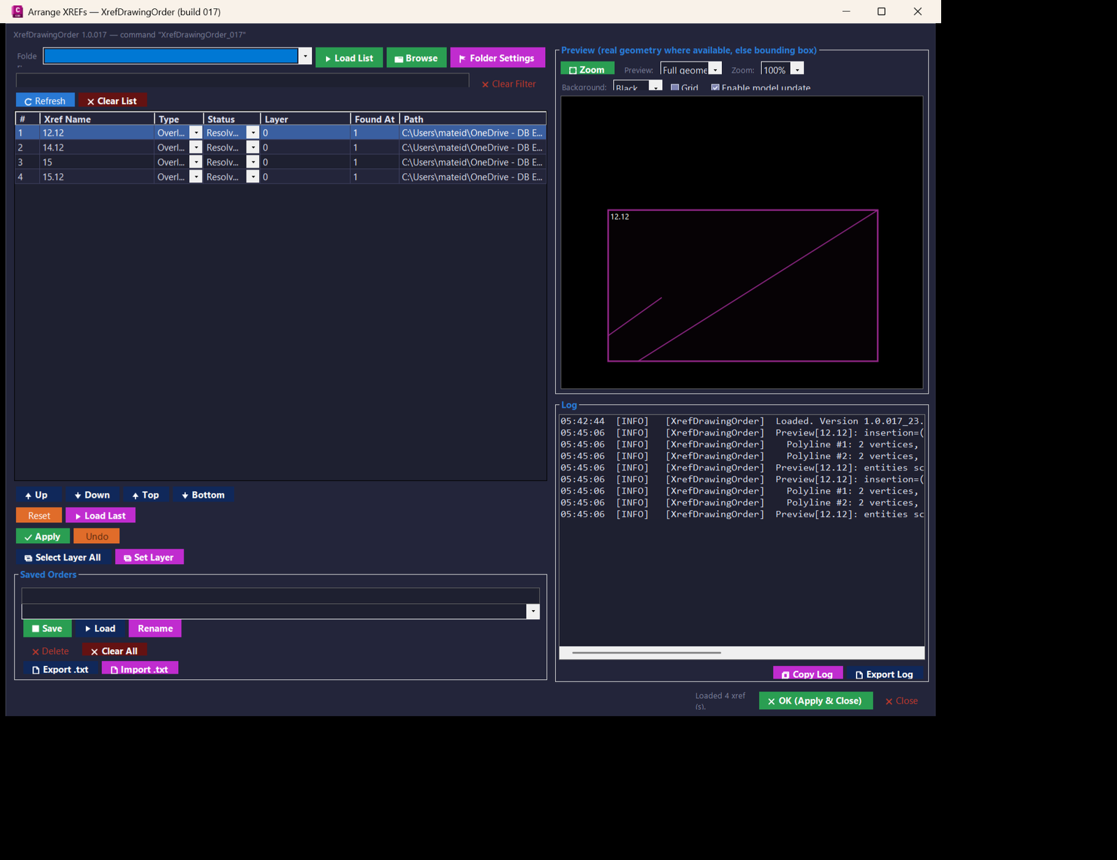
XrefsDrawingOrder
🧭 XrefDrawingOrder is an AutoCAD and Civil 3D xref draw order management plugin designed for drawings that contain many external references. It replaces repetitive manual DRAWORDER work with a searchable, reorderable, modeless WinForms interface.
📌 The tool scans the active drawing database for XREF block table records, lists their name, attach or overlay type, status, layer, instance count, and saved path, then allows the user to arrange the front-to-back display order from a central dialog.
🎯 It is useful for CAD managers, Civil 3D production teams, infrastructure designers, railway design users, corridor plan creators, and AutoCAD users who need cleaner xref stacking, faster xref visibility control, and repeatable drawing-order standards across project drawings.
🧩 Version 017 adds stronger preview diagnostics for selected xrefs, including insertion point, rotation, X and Y scale, transformed local coordinates, entity counts, and segment tracing for Line, Polyline, Circle, and Arc geometry. This helps diagnose difficult preview cases where a rotated or scaled xref appears incorrectly in the preview panel.
🖼️ The preview panel supports bounding-box visualization, selected-xref focus, mouse-wheel zoom, grid display, background switching, fast versus full preview mode, and fallback behavior when real geometry extraction is not available.
💾 The plugin can store the last used order in the drawing Named Objects Dictionary and can also save named order presets in the user AppData folder, making common xref display arrangements reusable between AutoCAD sessions.
⚙️ Xref ordering is applied safely from the modeless dialog by queuing AutoCAD DRAWORDER commands through Document.SendStringToExecute. The command sequence builds handle-based selection sets so each xref instance is targeted directly and selection-set race conditions are avoided.
Multiple_text_mtext_2
• Text collection: Builds an internal list of the text strings from all selected TEXT and MTEXT entities in the selection set. • Underline conversion: Scans each string for “%%U” underline markers and replaces them with MTEXT underline codes using L and l so underlining is preserved correctly. • Paragraph handling: For plain TEXT entities, prefixes each string with P so every original DText line becomes its own paragraph inside the final MTEXT. • Concatenation: Concatenates all processed strings into one combined MTEXT content string in selection order. • Placement: Creates a new MTEXT object at the insertion point of the first selected entity, using its text width to define the wrapping width. • Property transfer: Copies key visual properties from the first entity to the new MTEXT such as Layer, Color, StyleName, and Height, as well as alignment and rotation. • Cleanup: After successfully creating the new MTEXT, deletes all original TEXT and MTEXT entities that were part of the selection. • No selection case: If no valid text objects are selected, prints a short message instead of doing any changes.Copy_to_Clipboard_Xref
• Nested Picking: Lets the user select entities *inside* blocks or complex structures using NENTSELP. • Entity Duplication: Each picked item is duplicated using ENTMAKEX so its text can be extracted independently. • Transformation: Applies the exact nested transformation matrix so the copy matches the original nested orientation. • Text Extraction: Reads text differently depending on entity type: TEXT, MTEXT, DIMENSION, LEADER, or BLOCK attributes. • Clipboard Export: After finishing selections, CTCCOPY extracts text from all temporary copies and sends it to the Windows clipboard. • Cleanup: Deletes all generated temporary entities after copying text so the drawing stays unchanged.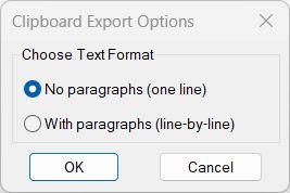
Copy_to_Clipboard
• Dialog Selection: Opens a DCL window where the user chooses one of two export modes for clipboard text. • Interactive Workflow: The last selected radio button option is remembered and pre-selected on the next run. • Text Extraction: Reads content from TEXT, MTEXT, DIMENSION, MULTILEADER, ATTRIB, ATTDEF, and blocks with attributes. • Formatting Cleanup: Removes U+ codes, inline MTEXT formatting, paragraph markers, and replaces them with clean characters. • Clipboard Output: Automatically transfers the cleaned text directly into the Windows clipboard via HTMLfile COM object.RotateMtextVport
This command adjusts text orientation based on the current viewport rotation:- MTEXT objects are reset to 0° rotation (horizontal) with top-left attachment point
- TEXT objects are rotated to match the viewport’s UCS X-axis angle with left alignment
Lower
• Selection: Prompts the user to select TEXT and MTEXT entities to be modified. • Case Option: Lets the user choose between converting to Upper or Lower case, with Upper as the default when Enter is pressed. • Processing: Reads each entity’s text content, converts it, and writes the new value back to the entity. • System Handling: Temporarily disables command echo and precision settings, restoring them afterward. • Failure Handling: Warns the user if no valid text entities are detected in the selection.Upper
This routine prompts the user to select TEXT and MTEXT entities, then reads every entity’s text content, converts it to uppercase using STRCASE, and rewrites the modified string back into the entity automatically.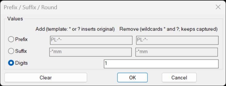
PrefixSuffixRound
The routine provides a DCL-based interface where you can choose between three actions: Prefix, Suffix, or Digits (rounding). Depending on the row selected, you can specify Add and Remove templates for prefix or suffix, or a number of digits for rounding numeric text. Prefix and Suffix operations support both fixed strings and wildcard templates that can capture parts of the original text and reinsert them using “*” and “?” placeholders, while the Remove side can strip matching patterns or wildcards from the beginning or end. The rounding option scans text content and converts numeric-only strings to rounded values with the specified number of decimal digits, leaving nonnumeric text unchanged. All operations can be reused without reopening the dialog by calling the PREF, SUFF, or OKR_TXT helper commands that rely on stored values.PlusMinusNumericValue
The routine opens a compact dialog where you enter a numeric increment/decrement value and specify which numeric segment(s) in the text to modify (by position, All, or via a later List prompt). It then scans the selected annotation objects, breaks each string into alternating numeric and non-numeric chunks, and applies the requested numeric adjustment to the chosen chunk(s) only, leaving surrounding text intact. For attributes, you can choose whether to modify the Tag or the Text string; for MTEXT, it respects basic control codes so numbers are not broken by formatting sequences. All changes are grouped in a single UNDO mark and the last-used dialog values are remembered via registry for the next run.Region2Polyline
The routine collects all REGION entities and processes them one by one by exploding each REGION into its primitive components — lines and arcs. It reorders these exploded segments so that they form a continuous closed loop, maintaining correct sequencing and connectivity between endpoints. For ARCs, it computes the corresponding bulge value using the arc’s total angle, allowing reconstruction of the curvature when converting back to LWPOLYLINE format. After ordering segments, it builds a new closed LWPOLYLINE from the reconstructed point list, applies bulges where needed, restores the elevation and normal vector, and then deletes the original REGION geometry.CopySelection
The user selects an LWPolyline and then two points projected onto its geometry to define the segment to duplicate. A dialog appears allowing layer filtering, picking from a list, or selecting an object in the drawing to adopt its layer. The code calculates curve parameters between the two points, reconstructs only that portion with widths and bulges, and creates a new LWPolyline on the chosen layer.CopySelection_vs.03
📍 The user first selects one or more supported curves and then specifies two points that define the source segment to duplicate.
🎯 The curve nearest the first picked point becomes the reference curve and the same picked start and end locations are projected onto every selected curve.
🧬 LINE ARC and legacy POLYLINE source geometry is converted temporarily into lightweight polyline form so the requested segment can be reconstructed.
🎛️ The new geometry can remain on the source layer or be assigned to another non Xref layer selected from a filtered layer list or picked from the drawing.
🔄 Extra mode can rotate the copied segment by a user defined angle around the selected start or end reference and move it laterally by a user defined distance.
📐 Extra 02 performs the extended and shifted workflow without rotation.
➡️ Start plus Left and End plus Right control the rotation reference and side orientation used by the transformation workflow.
📏 Extend Start and Extend End can lengthen the created lightweight polyline before the optional offset copies are generated.
📚 Offset presets include Profile_003 Profile_002 I Profile_002 II Profile_002 III Profile_002 IIIa and Profile_002 IV values together with a manually editable offset distance.
🔢 Offset Count can create up to twenty additional parallel copies.
🔗 CloseParallelPolylines can process created polylines in pairs by adding endpoint connectors and joining them through PEDIT.
➗ Create centerline polyline can generate an additional centerline between paired created polylines when the close workflow is enabled.
💾 The routine stores many last used settings with setenv and stores the DCL window position with setcfg.All_inside
⭕ For a selected circle the routine approximates the circular Window Polygon boundary with 90 points at four degree intervals.
📐 For a selected LWPOLYLINE the routine sends its DXF group 10 vertices to the AutoCAD WP selection option.
🔗 Results from multiple bounding circles and polylines are accumulated into the active selection set.
➕ The selected boundary objects themselves are added to the resulting set.
📦 The final prompt offers Yes or No for creating an AutoCAD group from the complete set.
🧭 The source comments reference CADStudio CADforum and a CADTutor discussion about selecting objects inside multiple polylines.LoadRecent
🧩 LoadRecent is an AutoCAD AutoLISP DCL manager for finding reviewing loading running editing and promoting recently created LSP files from a predefined @try development folder.
🎛️ The interface separates the newest LISP file from the complete file list and displays file size creation date modification date and detected commands.
📦 Version 06 also adds promotion into the Help_File menu structure with optional source deletion loader registration and timestamped loader backup.loadedDLLFiles
🧩 @loadedDLLFiles is an AutoLISP utility for loading and unloading a predefined group of AutoCAD and Civil 3D .NET DLL assemblies.
⚙️ The loader builds each DLL path from the current USERPROFILE value and a predefined relative OneDrive path then calls NETLOAD for files that exist.
📋 Successfully loaded DLL paths are stored in the global *loadedDLLFiles* list so the companion unload command can later call NETUNLOAD on the tracked assemblies.CheckParens
🧩 CheckParens is an AutoCAD AutoLISP validation tool for checking opening and closing parenthesis balance in a selected LSP source file.
🎛️ A DCL folder chooser lets the user select between @try AutoCAD and Civil 3D categories before choosing the LISP file.
🔎 The scanner ignores semicolon comments outside strings and counts parentheses outside quoted strings to identify an early extra closing parenthesis and the final balance.CheckLspFile
🧩 CheckLspFile is an AutoCAD AutoLISP diagnostic utility for scanning a selected LSP source file for reader level syntax errors.
📂 The command opens a file selection dialog rooted in a predefined @try folder and allows the user to select an LSP file for validation.
🧪 The routine reads the file one line at a time and tests each line with the AutoLISP read function inside protected error handling.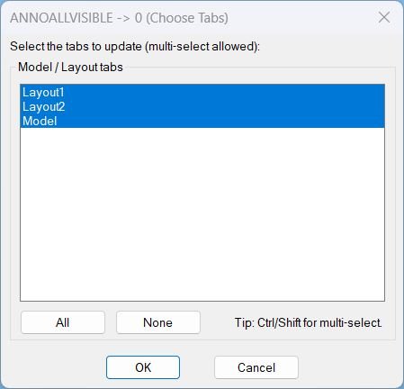
AnnoAllOff
🔇 AnnoAllOff is an SEO-friendly AutoCAD annotation visibility control tool for managing annotative object display across Model Space and Paper Space layouts.
🧩 The routine dynamically writes a temporary DCL file, lists all layout tab names from the active drawing, selects all tabs by default, and lets the user choose All, None, or a custom multi-selection.
📐 For each selected tab, the command switches CTAB to that tab, forces Paper Space when required, runs ANNOALLVISIBLE 0, and then restores the previous CTAB, TILEMODE, and MSPACE state.
📌 This is useful for AutoCAD and Civil 3D production drawings where annotative objects, labels, text, dimensions, and multileaders need controlled visibility per tab before review, plotting, or cleanup.
🧠 The script notes that ANNOALLVISIBLE is stored per Model tab and per Layout tab, not per viewport entity.SelectLayout
📑 SelectLayout is an SEO-friendly AutoCAD layout navigation tool for drawings with many paper space tabs.
🧰 The command reads the Layouts collection, excludes Model, builds a temporary DCL list box, and lets the user select one layout by name.
🚀 After confirmation, the routine runs AutoCAD layout switching logic to make the selected layout current.
🎯 This is useful for Civil 3D sheet sets, large drawing packages, layout-heavy DWG files, and fast paper space navigation.GoToLayout
📑 GoToLayout is an SEO-friendly AutoCAD layout navigation tool for drawings with many paper-space tabs.
🔍 The routine dynamically creates a Go To Layout DCL dialog with a wildcard layout-name filter, a match counter, a list of matching tabs, and Previous and Next buttons.
👁️ The Preview switch can update CTAB while the user browses the results, making it easier to visually inspect layout tabs before choosing the final destination.
🧠 The last used filter pattern is remembered across command runs through the global variable *gtl:lastpat*.
🛡️ If the dialog is cancelled, the routine restores the original layout tab so accidental browsing does not leave the drawing on the wrong sheet.
📌 This is useful for Civil 3D plan sets, DWG files with many layouts, sheet navigation, plotting preparation, and layout quality-control checks.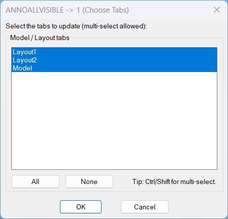
AnnoAllOn
- Generates a temporary DCL dialog at runtime listing all tabs, including Model, with multi-select enabled.
- On confirmation, switches to each selected tab and runs ANNOALLVISIBLE with value 1 to enable annotation visibility for that tab.
- Preserves and restores user context by saving CTAB, TILEMODE, and MSPACE before changes, then restoring them afterward.
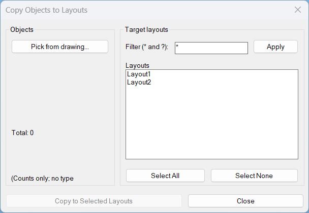
Copy2Layouts
📄 Copy2Layouts is an SEO-friendly AutoCAD layout copy tool for duplicating selected drawing objects to multiple Paper Space layouts in the current drawing.
🧰 The routine builds a temporary DCL interface with a Pick from drawing button, total object count, target layout list, wildcard layout filter, Select All / Select None, Copy to Selected Layouts, and Close.
🔍 The layout filter supports * and ? wildcards, making it easier to copy details only to selected layout naming groups such as 01*, A-??, plan sheets, or detail sheets.
🧠 The tool converts selected enames to VLA objects, builds a safe array, and calls vla-CopyObjects into each selected layout’s Paper Space block.
📌 This is useful for Civil 3D sheet notes, north arrows, legends, revision clouds, symbols, stamps, details, and other repeated paper-space annotation objects.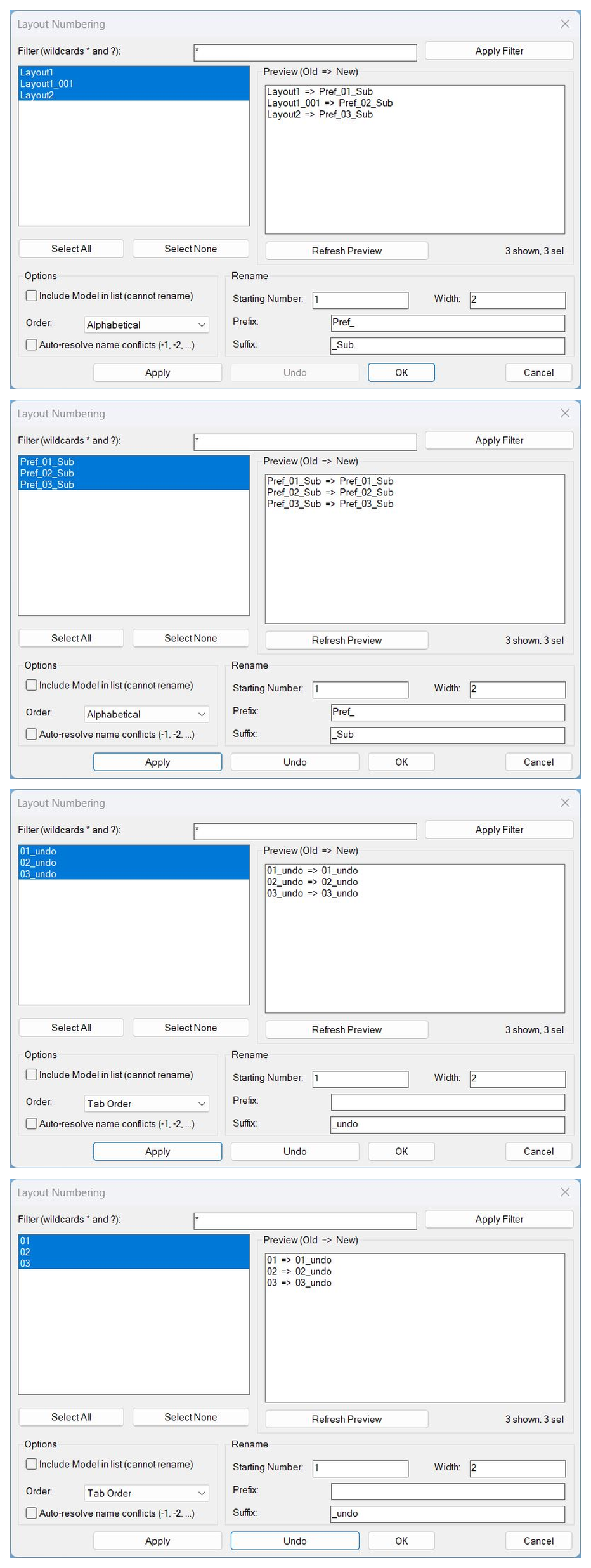
LayoutNum
🔢 LayoutNum is an SEO-friendly AutoCAD layout renaming and layout numbering tool for production drawings with many paper-space tabs.
📑 The routine builds a temporary DCL dialog titled Layout Numbering with wildcard filter, multi-select layout list, preview panel showing Old to New names, Select All, Select None, Apply, Undo, OK, and Cancel.
🧮 Users define the starting number, numeric width, prefix, suffix, and order mode to generate consistent layout names for Civil 3D sheets and AutoCAD plotting tabs.
🧠 The tool supports tab-order or alphabetical processing, optional inclusion of Model for reference, automatic conflict resolution using -1, -2 style suffixes, and persistent defaults for repeated runs.
🛡️ The code intentionally avoids calling AutoCAD UNDO from DCL callbacks and instead uses a manual multi-level undo stack that restores previous layout names safely.
📌 This is useful for batch layout renaming, sheet numbering, drawing package cleanup, plan set standardization, plotting tab organization, and Civil 3D production-sheet management.LockAllVp
🔒 LockAllVp is an AutoLISP / Visual LISP utility for batch locking and unlocking PaperSpace viewports across selected AutoCAD layouts.
🧭 It is designed for sheet-production workflows where plotted layouts must keep their viewport scale, pan, and orientation protected.
📋 The routine builds a custom DCL dialog, lists layouts in tab order, shows viewport status per layout, and lets the user lock or unlock selected layouts without repeatedly switching tabs.
🛡️ It uses ActiveX DisplayLocked on AcDbViewport objects and avoids calling -VPORTS directly inside DCL, reducing command-context instability.Zoom Extend
🔎 Zoom_Extend is an SEO-friendly AutoCAD layout zoom utility for batch paper space display cleanup.
📑 The command presents a DCL list of layouts, supports selected layout processing, and runs Zoom Extents on the chosen tabs.
📋 Clipboard support lets users copy selected layout names for reporting or QA notes.
🎯 This is useful for Civil 3D sheet files where many paper space layouts need their view extents reset before plotting, review, or publishing.Zoom Window
🔎 ZEZW is an SEO-friendly AutoCAD layout view management utility for batch zoom operations in paper space.
📑 The command builds a unique DCL dialog, lists layout tabs, supports wildcard filtering with * and ?, and lets the user select multiple layouts.
🪟 Users can run Zoom Extents or define a Zoom Window workflow after the dialog closes for more stable command execution.
🎯 This is useful for plotting preparation, layout QA, Civil 3D sheet checking, and drawing cleanup before publish or PDF export.All_Layouts_list
📋 All_Layouts_list is an AutoLISP DCL utility that lists all AutoCAD layouts in tab order and helps users copy selected layout names to the Windows clipboard.
🔍 It is built for sheet-management tasks where layout names must be reviewed, filtered, exported, or pasted into reports, publishing tools, Excel, or QA checklists.
🧭 The dialog supports wildcard filtering, optional Model tab inclusion, multi-selection, Select All, Select None, selected count feedback, and clipboard export.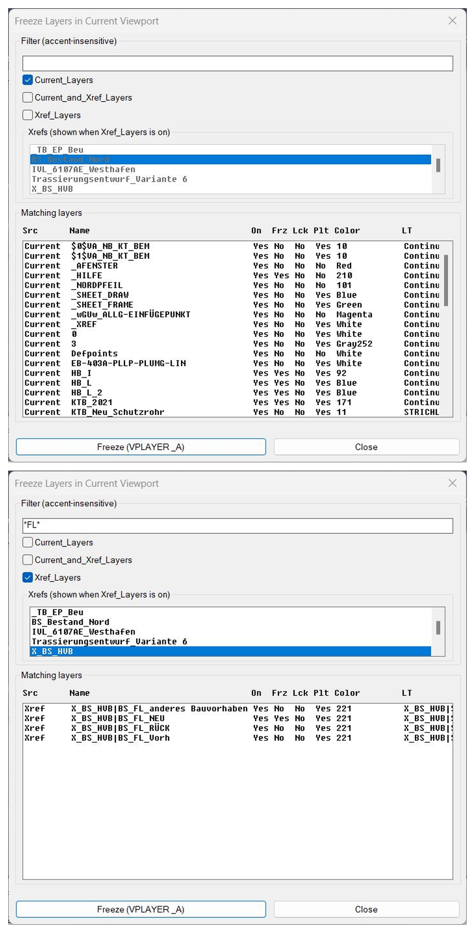
FreezeLayersInVP
❄️ FreezeLayersInVP is an SEO-friendly AutoCAD viewport layer freeze tool for managing layer visibility in paper-space viewport production.
🧊 The routine opens a DCL dialog with a layer name filter, source toggles for Current, Current and Xref, and Xref layers, plus an xref picker for narrowing the displayed xref layer list.
🔍 The list uses faux columns for Src, Name, On, Frz, Lck, Plt, Color, LT, and Desc so the user can review layer status before freezing.
🌐 The filter supports wildcard-style layer searching and includes accent-insensitive normalization for German and Latin characters.
🧩 After confirmation, the selected layer names are passed to AutoCAD VPLAYER Freeze using command logic equivalent to VPLAYER freeze layer all viewports based on the current implementation.
📌 This is useful for Civil 3D sheets, xref-heavy layouts, plan production, viewport cleanup, layer visibility coordination, and fast paper-space layer management.
TitleBlocksTools
This integrated toolset combines CSV export and import functionality for titleblock attribute management:- Main Menu Dialog provides radio button selection between Export and Load CSV operations
- EXPTBCSV_EXPORT – Exports titleblock attributes to CSV format from paper space inserts:
- User picks titleblock inserts interactively until pressing ENTER
- Collects all instances across all paper space layouts
- Displays available attribute tags with numbered list
- Allows tag selection via “All”, “None”, or range syntax (1,3,5-7)
- Outputs CSV with columns: DWG, Layout, Block, plus selected tags
- Handles Excel-problematic values (dates, formulas) with single-quote prefix
- Escapes commas, quotes, and newlines using proper CSV quoting
- Auto-opens in Excel via hard-coded path with registry and fallback detection
- UTB2 – Updates titleblock attributes from CSV (Lee Mac’s Update Titleblock V1.9):
- Matches current drawing name against first column of CSV
- Optional Layout column filter for layout-specific updates
- Optional Block column filter for block-specific updates
- Updates only attributes whose tags match CSV column headers
- Changes only when attribute values differ from CSV
- Supports dynamic blocks via effective name resolution
- Handles duplicate attribute tags correctly
- Single UNDO mark for entire operation
- Configurable block name wildcard filter (UTB2:ftr)
- Can run automatically on drawing open (commented by default)
- Enhanced Help Dialog with comprehensive documentation:
- Displays LISP file path and full usage instructions
- Unicode/ASCII toggle for bullet points and arrows
- Multi-select list with Copy Selected and Copy All to clipboard
- Copy Path button for LISP file location
- Integrated Explorer and Notepad++ launcher buttons
- Explains CSV format, column requirements, and workflow
- File Management Tools:
- Explorer button opens folder containing LISP file with file pre-selected
- Notepad++ button opens LISP in editor (detects installation paths)
- Reload button reloads LISP file from disk without closing AutoCAD
- Path resolution via %USERPROFILE% environment variable
- Persistent Settings – Remembers last selected option and Unicode preference across sessions
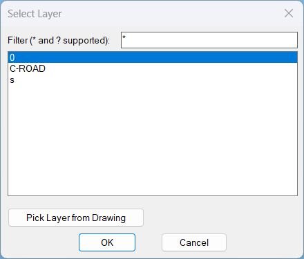
Zoom2Layer
- Builds a list of layers that are visible and unfrozen, then shows a temporary DCL popup where the user can filter and select a layer.
- The filter field supports wildcards * and ? and is restored from the environment variable CHLAY-LAST-FILTER (defaults to *).
- After a layer is selected, the command gathers all entities on that layer and computes a combined bounding rectangle, then performs a window zoom to that area.
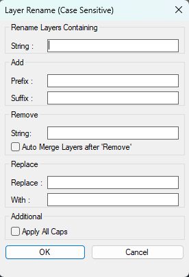
RenameLayer
🧱 RenameLayer is an AutoCAD layer renaming tool designed for fast, controlled, repeatable layer name editing in production drawings.
🔎 The routine scans the active drawing layer table and builds a filtered list of local layers, excluding layer 0 and xref-dependent layers that contain the xref separator character |.
🪟 A custom DCL dialog provides a searchable multi-select layer list, filter box, Add controls, Remove controls, Replace controls, ALL CAPS conversion, Auto Merge option, Apply button, OK button, and Cancel button.
🧰 CAD users can add prefixes, add suffixes, remove unwanted text strings, replace old layer name fragments with new strings, or use wildcard-style replacement patterns to restructure layer names.
🔁 The Apply button performs the rename operation and reopens the dialog workflow, making it practical to apply multiple rename passes without restarting the command.
✅ If no layers are selected in the list, the tool processes all currently visible filtered layers, allowing quick batch rename operations after using the Search filter.
🔀 When Auto Merge is enabled and the target layer name already exists, the routine uses the AutoCAD LAYMRG workflow to merge the source layer into the destination layer instead of failing the rename.
🧠 The rename operation is wrapped inside an AutoCAD undo mark so the user can roll back the complete rename or merge pass as a single grouped action.
📌 This is especially useful for CAD standards migration, client layer naming conversions, imported DWG cleanup, Civil 3D production drawings, survey layer cleanup, xref layer normalization, and office template maintenance.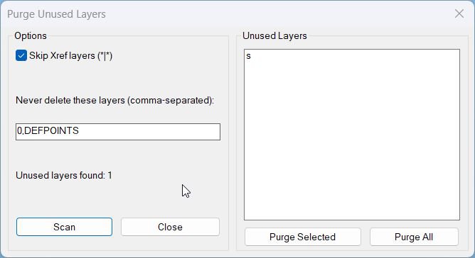
PurgeUnusedLayers
🧹 This AutoCAD layer purge tool scans the active drawing layer table and identifies layers that have no entities assigned to them.
🎛️ The embedded DCL dialog is written to the temporary folder each run and shows options, status text, and a multi-select list of unused layers.
🔒 The default protected list includes 0 and DEFPOINTS, and the user can add more comma-separated layer names that must never be deleted.
🔗 A Skip Xref layers option protects xref-dependent layers containing the | separator.
🗑️ The user can run Scan, then Purge Selected or Purge All from the dialog.
📊 After deletion, the command reports how many layers were deleted and how many failed to delete.LayersNameToClipboard
📋 This AutoCAD command collects selected objects, converts them to VLA objects, and reads the Layer property where available.
🧹 The StripSimpleCodes helper removes backslash-based formatting codes from text before the layer name is stored.
🔎 Duplicate layer names are ignored so the final result contains each layer only once.
📄 The layer list is converted into newline-separated text, printed in the command line, and copied to the Windows clipboard.
⚙️ Clipboard output is created through the Windows htmlfile ActiveX clipboardData interface.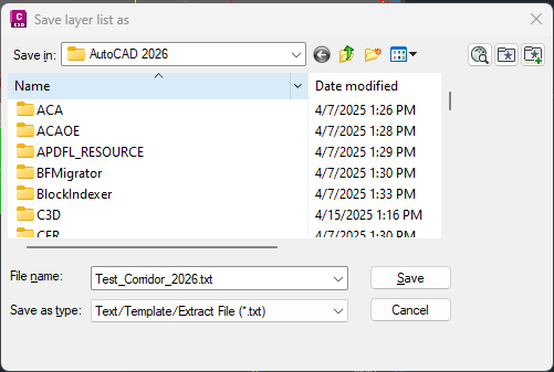
LayerList
📘 LayerList scans the
Layerscollection of the active AutoCAD drawing and builds a sorted layer report that can be opened in a text editor or imported into Excel for CAD standards checking.The user runs
LLFP, chooses an output file path withgetfiled, and the program writes a layer table using the current drawing name as the default report filename. The exported report includes practical AutoCAD layer management data such as layer name, visibility, freeze state, locked state, color, linetype, lineweight, plot style, plottable status, and viewport default freeze setting.This AutoLISP utility is useful for DWG cleanup, CAD coordination, Civil 3D project review, plotting diagnostics, layer standard audits, and quick layer documentation. It is a non-destructive reporting tool: it reads layer properties and creates an external text file, but it does not modify the drawing geometry or change layer settings.
Import_Layer_Filter
📥 Import_Layer_Filter is an SEO-friendly AutoCAD layer filter import and export utility for moving property layer filters between drawings, templates, and project folders.
🧱 The routine reads AutoCAD ACAD_LAYERFILTERS and ACLYDICTIONARY data, exports selected filters to .lft files, and reconstructs filters in another drawing.
📦 The enhanced v2 .lft format supports multiple layer filters in one file with a //COUNT header, while the importer still handles older single-filter v1 files.
🗂️ A project folder preset manager stores frequently used Layer_Status paths and allows reordering, saving to file, reloading the LISP, and selecting default import or export locations.
📌 This is useful for CAD managers, Civil 3D project teams, layer-standard migration, xref filter reuse, and template synchronization.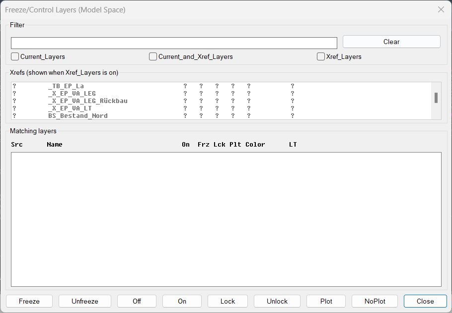
FreezeLayersInMS
❄️ FreezeLayersInMS is an SEO-friendly AutoCAD layer visibility manager for controlling local and xref layer states from a custom DCL dialog.
🔍 The dialog includes a name filter, xref filter, xref multi-selection list, and a matching-layers table with source, layer name, on/off state, freeze state, lock state, plot state, color, and linetype.
🧠 Xref layer names are displayed without the xref| prefix to keep the list readable, but operations still use the true full layer names internally.
📌 This is useful for Civil 3D model-space cleanup, xref coordination, layer QA, plan-production visibility control, and project-layer standard management.Export_Layer_Filter
📤 Export_Layer_Filter is an SEO-friendly AutoCAD layer filter export utility for transferring property layer filters between drawings and projects.
🧱 Based on the gile layer filter export and import concept, this enhanced version writes selected AutoCAD layer filters to an .lft file using a v2 multi-filter format with a //COUNT header.
🔤 Prefix and suffix controls can modify NAME== patterns in the exported filter expressions, making the workflow practical for xref-layer naming standards such as DrawingName|LayerName.
🗂️ Predefined folder shortcuts help store layer-filter exports in project Layer_Status directories instead of manually browsing every time.
📌 This is useful for Civil 3D project templates, xref layer visibility standards, layer-state administration, CAD QA checks, and drawing setup automation.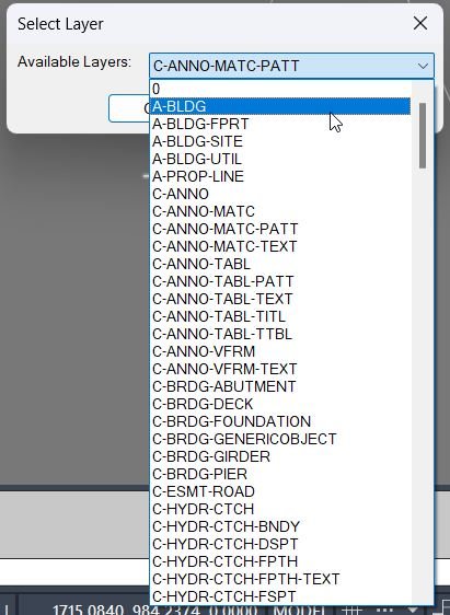
DuplicateToSelectedLayer
📋 DuplicateToSelectedLayer is an SEO-friendly AutoCAD layer copy tool for duplicating existing drawing objects onto another layer without moving their geometry.
🧱 The routine collects a selection set with ssget, shows only non-xref layers in a sorted DCL popup list, and then copies the selected entities using zero displacement.
🎯 After the copy operation, the new entities are moved to the chosen layer with CHPROP, sent to the front using DRAWORDER, and left selected for immediate review.
📌 This is useful for Civil 3D production drawings, CAD layer cleanup, visual alternatives, temporary design copies, layer standardization, and controlled duplication workflows.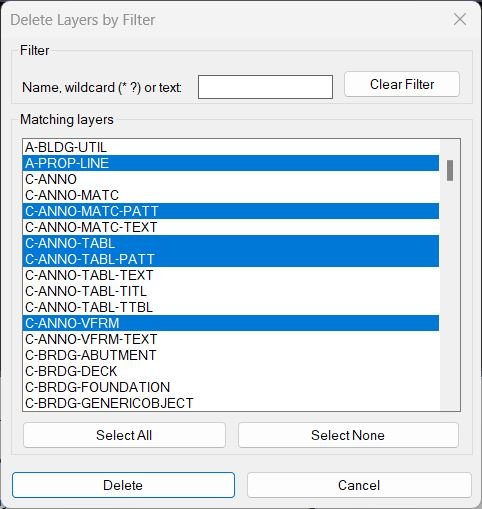
DeleteLayerByFilter
🧹 DeleteLayerByFilter is an SEO-friendly AutoCAD layer cleanup tool for deleting unwanted layers through controlled wildcard matching.
🔎 The routine scans the active drawing layer table, applies up to five filter strings combined by OR logic, and displays the matching layer names in a multi-select DCL list box.
🔁 The inverse filter mode can show layers that do not match the current filters, which is useful for checking non-standard layer names or isolating unexpected CAD standards.
🛡️ Built-in protected layer patterns prevent deletion of critical layers such as 0, DEFPOINTS, xref layers, text layers, dimension layers, Civil 3D surface layers, COGO point layers, alignments, profiles, sections, corridors, pipe networks, structures, parcels, viewports, and xref-related layers.
📤 Export functions allow the user to write selected, displayed, or all matching layer names to a TXT file before deleting anything.
🧠 The embedded DCL is written line by line to a temporary .dcl file, avoiding AutoLISP string-length loading errors while keeping the tool as a single-file LISP application.
⚠️ Because this tool deletes drawing layers, it includes confirmation before destructive operations and reports deleted, protected, and failed layer names.Color2Llayers
🎨 Color2Llayers is an SEO-friendly AutoCAD layer color changer and CAD standards utility.
🔍 The XCC dialog shows layer rows with flags, layer names, color, and linetype information, plus a wildcard filter that supports * and ?.
🎯 Users can multi-select layers, choose Pick Color, click Apply, and immediately see changes after the dialog safely closes and reopens using done_dialog 2 and REGENALL.
↩️ The routine stores an undo snapshot before writing layer color changes and supports an Undo button inside the dialog.
📋 A Copy to Clipboard button exports layer name, color, and linetype rows through a temporary tab-delimited file and Windows clip.exe when available.
💾 Dialog X/Y position and filter text are saved with getcfg/setcfg for the next session.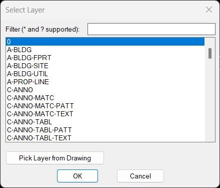
ChangeLayerToCurrent
🗂️ ChangeLayerToCurrent is an SEO-friendly AutoCAD layer management tool for changing selected objects to a selected drawing layer.
🔍 The command builds a temporary DCL dialog, lists all layers, supports a filter text box, and remembers the last selected layer and filter using environment variables.
🎯 A Pick Layer workflow lets the user select an existing object and reuse its layer as the target layer.
📋 A Copy Layer Name helper sends the chosen layer name to the Windows clipboard through PowerShell/clip logic.
🧠 The optional Keep original properties mode captures effective linetype, linetype scale, and lineweight/width before moving objects, then reapplies those values after the layer change.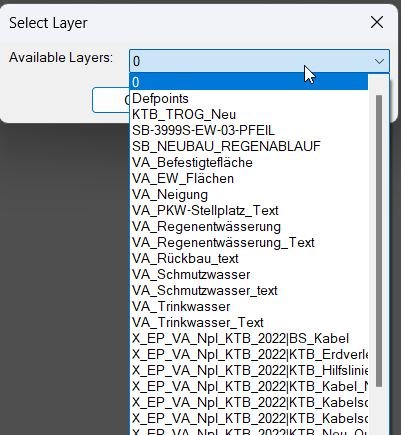
ChangeLayerToSelected
- Reads the last used layer and last filter from environment variables ChangeLayer_LastLayer and ChangeLayer_LastFilter to initialize the dialog state.
- Builds a sorted list of all drawing layers excluding Xref layers (names matching *|*).
- Creates a temporary DCL dialog with a filter edit box, a popup list of matching layers, and a button to pick a layer from an object in the drawing.
- When the user clicks OK, stores the chosen layer and filter back to the environment, then proceeds to object selection and changes those objects to the chosen layer via CHPROP.
- If the user clicks Pick Layer From Drawing, the routine prompts for an object, captures its layer, and reopens the dialog with that layer preselected (while retaining the last filter text).
All_Color2Layers
🎨 All_Color2Layers is an SEO-friendly AutoCAD entity cleanup utility for resetting object color and linetype overrides to BYLAYER.
🧰 The BYLAYERDLG command writes a temporary DCL dialog with Color only, Linetype only, and Both operation modes.
🗂️ The dialog includes scope toggles for Model Space, Paper Spaces, and Block Definitions, plus a layout filter and multi-select list.
↩️ Apply creates an undo mark and the custom Undo button reopens the dialog after running AutoCAD UNDO 1.
🔍 The code unlocks locked layers temporarily, processes non-xref blocks/entities, restores layer locks, and stores dialog settings with getcfg/setcfg.SplitHatch
✂️ SplitHatch is an SEO-friendly AutoCAD hatch separation routine for CAD cleanup and hatch editing workflows.
🟧 The command selects HATCH entities and applies AutoCAD HATCHEDIT with the Separate option to each selected hatch.
📐 The source comment indicates the routine separates multi-boundary hatches while keeping hatch angle and scale.
🧹 It is useful when one hatch object contains multiple boundaries and those boundaries need to become separate editable hatch objects.
🚀 The implementation is intentionally small and relies on AutoCAD’s native hatch editing command.MleaderStraight
📐 MleaderStraight provides an SEO-friendly AutoCAD MLeader alignment workflow for CAD users who need cleaner annotation geometry, straighter leader lines, and more consistent Civil 3D drafting presentation.
🧩 The routine reads the first leader-line vertices from each MULTILEADER, determines whether the leader is closer to a horizontal or vertical adjustment, and rewrites the leader vertices so the resulting segment is orthogonal.
🖱️ A temporary embedded DCL dialog lets the user choose between interactive selection and all MultiLeaders in the current drawing space.
🗂️ The routine is ModelSpace and PaperSpace aware: it uses the active document space object for temporary construction geometry and uses CTAB to target the correct layout when processing all leaders.ConvertLeaderAndText2Mleader
🚀 ConvertLeaderAndText2Mleader is an AutoCAD and Civil 3D AutoLISP utility that converts a selected legacy LEADER and MTEXT pair into a clean MLEADER object. The tool helps modernize old drawing annotations, reduce manual leader rebuilding, and keep CAD documentation consistent when updating legacy DWG files. It can optionally use an existing MULTILEADER as the style source, preserve MTEXT rotation, transfer text width and layer behavior, and erase the original LEADER and MTEXT after creating the new MLEADER.
AddVertex2Mleader
📝 AddVertex2Mleader is a compact AutoCAD LISP command for editing multileader geometry by inserting an additional leader vertex into the selected leader line.
The routine prompts the user to select a MULTILEADER entity, asks for a new point, reads the existing leader line vertices through Visual LISP COM methods, and rebuilds the vertex list with the picked point inserted near the closest existing segment location.
This is useful for CAD annotation cleanup, Civil 3D drafting corrections, drawing coordination, and fast leader adjustment when labels need to be routed around objects, xrefs, dimensions, hatches, or congested drawing details.
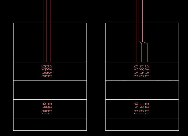
FixLineTextOverlap
📘 FixLineTextOverlap is designed for AutoCAD drawings where vertical service lines, schematic connections, utility labels, or annotation groups overlap horizontally and become difficult to read. The program arranges selected vertical LINE objects around a picked crank point, then optionally applies the same spacing logic to nearby text so the geometry and labels remain coordinated.
🔍 The workflow starts by selecting vertical LINE entities and picking a crank point. The picked point defines the reference Y level and the rail X location used for the step-out arrangement. The code calculates a default spacing from the current drawing text size, then allows the user to override it for line spacing.
🧠 After line cleanup, the text workflow can select TEXT and MTEXT entities and use the same spacing and rail position. Text is grouped by Y row, split to the left and right side of the rail, anchored at the nearest item, and stepped away in equal intervals to remove overlap while preserving row readability.
📐 For lines, the routine creates LWPOLYLINE crank geometry using entmakex, deletes the original LINE entities, and keeps the output on the source layer. For text, it updates insertion points through entmod and entupd while respecting TEXT justification and MTEXT insertion behavior.
🛡️ The tool wraps edits in an AutoCAD UNDO group so the complete line and text cleanup operation can be reverted in one step.
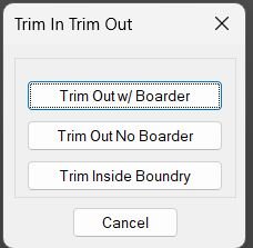
TrimIn_TrimOut_Boundary
TrimIn_TrimOut_Boundary is an AutoLISP boundary-cleanup routine based on the enhanced multi-trim SECTION workflow by Bob Jones with a dialog interface added by Jim Arthur. It prompts the user for two rectangle corners and then trims and erases geometry either outside or inside the rectangle.
The command can leave a rectangular polyline border, trim outside while deleting the temporary border, or delete and trim geometry inside the rectangle depending on the selected operation.
NCopyExtra
NCopyExtra is an AutoCAD AutoLISP utility designed to copy objects from attached XREF drawings into the current host drawing while preserving correct placement through transformation handling.
The main NCopyExtra command opens a DCL dialog first. From the dialog, the user can pick a rectangular selection area, identify or choose an XREF, filter the XREF list with wildcard text, select Crossing or Window mode, and control whether layer properties are copied, whether copied entities are placed on _hilfslinien, and whether the operation is wrapped in a single UNDO group.
The routine resolves the selected XREF path, opens the referenced drawing through ObjectDBX when needed, transforms the host selection rectangle into XREF-local coordinates, scans the XREF model space using bounding boxes, and copies the matching objects into the active drawing.
The included ClassicalNCopy command provides a direct one-by-one workflow using nentselp. It copies a picked nested object, applies the nested transformation matrix with vla-transformby, strips the XREF prefix from the layer name, creates the clean local layer when needed, and copies key layer properties from the XREF layer.
CopyMove2MidPoint
🚀 MTM2 provides a fast midpoint-to-midpoint workflow for AutoCAD drafting and Civil 3D production drawings.
📌 The tool lets the user select one or more objects, define a source reference with two picked points, define a destination reference with two picked points, and then move or copy the selected objects by the calculated midpoint vector.
📐 The source midpoint is calculated from the Y values of P1 and P2 while preserving the X and Z values from P1. The destination midpoint is calculated as a full 3D midpoint from P3 and P4.
🔄 The resulting translation vector is transformed from UCS to WCS before applying the move or copy operation, making the workflow suitable for drawings using custom UCS orientations.
🧱 Objects on locked layers are skipped to avoid modification errors during batch processing.CookieCutter2
CookieCutter2 is an AutoCAD and Civil 3D AutoLISP alternative to Express Tools EXTRIM, also known as CookieCutter. It accepts a circle or a closed polyline, ellipse, or spline as the trimming edge, then asks the user to pick the side to trim. Depending on the selected side, the routine can behave like EXTRIM or erase all objects on visible layers inside or outside the boundary.
The routine expands the trimming workflow by processing blocks, hatches, and regions. Intersecting blocks can be exploded recursively, nested block attributes can be converted to text, non-solid hatches and regions can be exploded, and solid hatches can optionally be converted to ANSI31 lines before trimming. Objects that cannot be trimmed are preserved or skipped according to their type.
CookieCutter2 temporarily unlocks locked non-xref layers, traces curved boundary geometry into point lists, detects inside and outside areas, calculates intersections with Visual LISP ActiveX IntersectWith logic, offsets the selected boundary to determine trim points, trims intersecting objects, restores the original view and system variables, relocks layers, and groups the operation inside an AutoCAD undo mark.
The included CookieCutter2Multi command adds a multi-boundary cleanup mode. It accepts several closed boundaries, builds the combined inside and crossing selections, protects the selected boundaries, and erases objects outside all selected areas. This multi-boundary mode performs outside erasing only and does not trim intersecting entities.

CenterAreaCentroid
📐 CenterAreaCentroid is an AutoCAD AutoLISP geometry utility that helps users create a point at the most inner area position of a closed shape or place a centroid label from a selected polyline-derived region. The tool opens a small DCL dialog named CenterAreaCentroid Options where the user can choose Center Area or Centroid before the calculation starts.
🎯 The Center Area workflow runs the MostInnerPoint2 routine. It asks the user to select a supported closed object, uses Visual LISP curve and offset logic, and places an AutoCAD POINT at the calculated internal position. This is useful when a user needs a practical label point inside a closed boundary, closed polyline, or planar closed spline.
🧭 The Centroid workflow runs get_centroid. It prompts for a polyline, converts it to a temporary REGION, reads the centroid through ActiveX, and inserts a TEXT label named CENTROID at the calculated location. This supports quick centroid marking for area-based CAD checks and drawing annotation.
TotalLengthPolyline
🚀 TotalLengthPolyline provides a fast AutoCAD length takeoff workflow for CAD drafting, Civil 3D production drawings, quantity checks, and geometry verification.
📐 The TLEN command prompts the user to select drawing entities, scans every selected object, calculates a length contribution for each supported type, sums the values, and reports the final total length in the current drawing units.
🔍 Lines are measured with point-to-point distance, arcs are calculated from radius and angle, and closed or curve-based entities such as circles, splines, polylines, lightweight polylines, and ellipses are processed through AutoCAD perimeter evaluation using the AREA command object option.
📊 The result is displayed in a simple AutoCAD alert window, making the routine useful when the user needs a quick total length check without tables, dialogs, Excel export, or MTEXT placement.

TotalLengthAreaDetailed_vs_01
What it does • Dialog choice Lets you choose between Length or Area, set Excel related options, and define decimal precision. • Entity selection Prompts you to select relevant entities, then sums their geometric length or area depending on the chosen mode. • Expression building Builds a term by term expression like v1+v2+v3 using the chosen decimal precision. • Excel output Converts the expression to =expression or =ceiling(expression,5) according to the selected Excel options and copies it to the clipboard. • MText creation If enabled, asks for an insertion point and creates MText in the current UCS reading either just the single value or the full expression with its total.TotalLengthAll
📏 TotalLengthAll is a lightweight AutoCAD AutoLISP length calculator designed to total the lengths of multiple curve-based drawing entities in the current drawing units.
🚀 Run ELEN to calculate the combined length of selected geometry such as LINE, POLYLINE, LWPOLYLINE, 3D POLYLINE, CIRCLE, ARC, ELLIPSE, and SPLINE objects.
🔍 The routine supports both pre-selected objects and command-driven selection. When unsupported objects are included in the selection set, the tool reports how many were filtered out and continues with the supported curve entities.
📊 The result is printed directly in the AutoCAD command line, showing the total number of calculated entities and the combined total length.
🧰 This is useful for CAD quantity checks, quick linear measurements, road or utility drafting reviews, preliminary takeoffs, and fast verification of multiple curve lengths without manually adding each object length.
TLength
📐 TLength helps AutoCAD and Civil 3D users measure combined object lengths quickly from the command line.
🚀 Run the TLENGTH command, select supported geometry, and the tool sums the total length or perimeter using AutoCAD ActiveX curve data. The result is printed in the command line and copied to the Windows clipboard as a clean numeric value with four decimal places.
🧰 Supported object types include LINE, POLYLINE, LWPOLYLINE, ARC, CIRCLE, ELLIPSE, SPLINE, MLINE, REGION, and MPOLYGON. This makes it useful for quantity takeoff, drafting checks, linear measurement control, Civil 3D production drawings, CAD auditing, and fast length reporting.
📋 The clipboard workflow makes it easy to paste the calculated value into Excel, reports, labels, schedules, quantity tables, BoQ calculations, or other downstream documentation.
SumLengthField
📐 SumLengthField generates associative AutoCAD FIELD expressions from selected geometry and writes the result into the drawing as annotation.
🔄 Because the output is FIELD-based, the displayed length or area can update when referenced objects change, after AutoCAD fields are refreshed.
🧩 The length workflow supports arcs, circles, lines, lightweight polylines, heavy 2D polylines, and 3D polylines.
🟧 The area workflow supports arcs, circles, ellipses, hatches, polylines, regions, and splines. Open objects are evaluated using AutoCAD’s area property behavior.
📝 The result can be inserted as new MText, written into a selected table cell, or pushed into existing Text, MText, Attribute, Attributed Block, or MLeader content.
🧠 For multiple selected objects, the routine builds an AcExpr field that sums all referenced object properties into one displayed total.
🔐 Undo marks are used so the operation can be reverted cleanly inside AutoCAD.PolylineArea
📐 PolylineArea helps AutoCAD users calculate the combined area of multiple selected polylines in one simple command.
🔍 The routine selects lightweight, 2D, 3D, and legacy polyline-type objects through the *POLYLINE selection filter.
🧮 For every selected polyline, the tool runs the native AutoCAD AREA command with the Object option and accumulates the drawing area value.
📋 The result is automatically copied to the Windows clipboard, making it easy to paste the calculated value into Excel, reports, quantity takeoff tables, BoQ worksheets, or project notes.
🏗️ This is useful for civil engineering, infrastructure drafting, CAD quantity checks, pavement areas, site layouts, closed boundary checks, land development areas, and AutoCAD production workflows.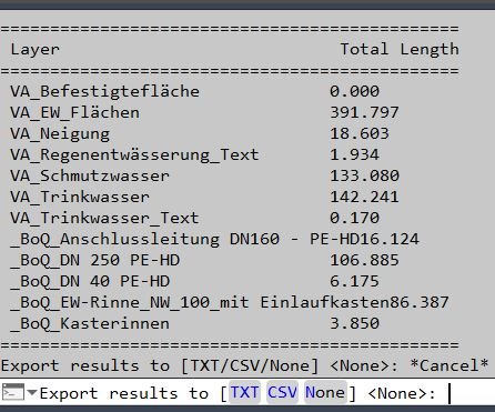
PLLengthByLayer
📏 PLLengthByLayer is an AutoCAD AutoLISP reporting tool that scans the active drawing for all LWPOLYLINE objects and summarizes their total length grouped by layer.
🚀 Run the PLLengthByLayer command to automatically collect every lightweight polyline in the drawing, read its layer name, calculate its object length through ActiveX, and build a layer-based total length table.
📊 The result is printed directly in the AutoCAD command line with each layer name and its accumulated polyline length, making it useful for CAD quantity checks, layer audits, design measurement review, road marking quantities, utility layout checks, and civil drafting production workflows.
📤 After the command-line summary, the tool can optionally export the results to TXT or CSV in the current DWG folder. The export uses a unique filename based on PLLengthByLayer so existing reports are not overwritten.
🧰 This routine is lightweight, non-destructive, and works as a quick AutoCAD length takeoff helper for drawings where layer names are used to separate design categories, disciplines, or quantity items.
LenCalc
📊 LenCalc is a dialog-based AutoCAD AutoLISP length calculator for quantity takeoff and drawing audit workflows.
🚀 The command scans supported curve entities, groups total lengths by Layer, Linetype, or Colour, and outputs the results as an AutoCAD table, TXT file, or CSV file.
🧰 It supports LINE, LWPOLYLINE, POLYLINE, ARC, CIRCLE, SPLINE, and ELLIPSE objects, with configurable object type toggles, wildcard filtering, table style selection, output format selection, precision control, and optional automatic opening in Excel or Notepad.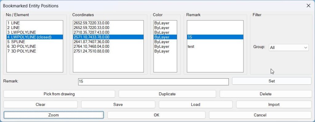
BookmarkEntities
Bookmark data structure: Each bookmark is stored in*bm-list*as:(label startPt endPt colorStr handle etype remark)• label – friendly name like “TEXT”, “LWPOLYLINE (closed)”, “BLOCK MyBlock”, etc., depending on entity type. • startPt – a representative start / lower point: – Lines: start point (10). – Polylines / splines: start point fromvlax-curve-getstartpoint. – Text / blocks / circles: usually lower bound of the bounding box, fallback to insertion point. • endPt – usually upper bound of the bounding box, used to define a zoom window. • colorStr – color info as text: – If TrueColor (DXF 420) exists:"TC:<integer>". – Otherwise: ByLayer / ByBlock / ACI number. • handle – entity handle (DXF 5) used later to find the live entity withhandent. • etype – DXF type string (“TEXT”, “MTEXT”, “LINE”, “LWPOLYLINE”, “POLYLINE”, “CIRCLE”, “SPLINE”, “INSERT”). • remark – user-defined comment, stored as simple string.
Global lists & filters: •*bm-list*– the full bookmark collection for the current session/drawing. •*bm-index-map*– maps visible row index in the dialog to the real index in*bm-list*(used when group-filtering so operations affect the correct entry). •*bm-group*– current group filter: “All”, “Text”, “Lines”, “Polylines”, “Circles”, “Splines”, “Blocks”, “Other”. •*bm-groups*– complete list of group labels, always starting with “All”. Built dynamically from current bookmark content.Exp_Imp_NamedViews
🧭 Exp_Imp_NamedViews is an AutoCAD LISP tool for transferring Named Views between drawings. It provides a dialog driven workflow for exporting current drawing view definitions to a TXT file and importing those saved view definitions back into another DWG.
📤 The export workflow scans the AutoCAD VIEW table, collects all named views, writes cleaned DXF data to a text file, and also exports linked VISUALSTYLE definitions once when a view references a visual style. This helps preserve view navigation settings and visual display configuration when moving view setups between drawings.
📥 The import workflow reads the exported TXT file, recreates VIEW records with entmake, rebuilds Visual Style records with entmakex where required, and writes the imported view names to the command line for quick verification.
🧰 The main DCL command ExpImpNVU provides radio buttons for Export NamedViews and Import NamedViews, a predefined folder popup, Explorer and Notepad++ helper buttons, a Reload button, and a Help dialog with clipboard support. It is designed for CAD users, Civil 3D teams, BIM coordinators, and CAD managers who need repeatable Named View transfer between project drawings.
💾 The tool remembers and reuses folders through a registry based workflow under HKEY_CURRENT_USER\Software\JTBWorld\viewsIO. It also supports GUI and command-line variants for both export and import.
Add_Bookmark
This routine lets you select a mixed set of supported entities and extracts a simple “label + start point + end point” triple for each, then pushes that triple into a global bookmark list for later processing by other tools or routines. For text and block inserts it uses their insertion point and a synthetic end point offset, for lines and splines it uses their defined endpoints, for polylines it uses the bounding box corners, and for circles it uses center plus a radius-based corner point. After all selected entities are processed, it reports the total number of bookmarked entries now stored, building up a reusable memory of object positions across multiple command runs.Clear_Bookmarks
This command displays a confirmation alert asking whether the user wants to clear all saved text positions. If confirmed, it removes all entries from *textPositions*, the list used to store entity bookmarks created by c:BMEntityPos. If the user cancels, the function safely exits without modifying existing data.
NamedViewList
📘 NamedViewList is a portable AutoCAD productivity tool for managing saved Named Views directly from a custom DCL dialog. It collects all named views from the active drawing, sorts them case-insensitively, and displays them in a multi-select list with live filtering.
🔎 The tool is designed for fast view navigation and drawing setup management. Users can filter view names, toggle Match case, zoom to a selected view without closing the dialog, delete selected views in place, rename a view by double-clicking it, and restore one or more selected views after pressing OK.
🧩 This utility is useful for CAD technicians, AutoCAD users, Civil 3D production teams, BIM coordinators, and CAD managers who work with many saved views in large drawings, sheet preparation files, corridor plans, xref coordination drawings, or discipline-specific production layouts.
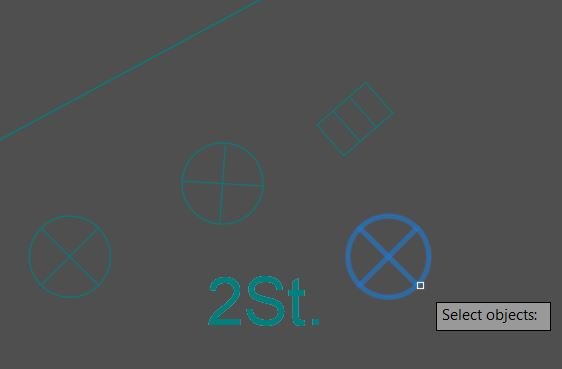
SwapBlockAssignLayer
🚀 SwapBlockAssignLayer is an AutoCAD AutoLISP block replacement tool for converting selected drawing entities into inserted block references.
The command prompts the user to select objects, displays a DCL popup list of available named blocks in the current drawing, remembers the last selected block through an environment variable, inserts the chosen block at each selected object’s insertion point or bounding-box center, and deletes the original selected object after replacement.
It is useful for CAD cleanup, converting placeholder geometry into standardized blocks, replacing temporary symbols with real block references, and improving drawing consistency in AutoCAD and Civil 3D production drawings.
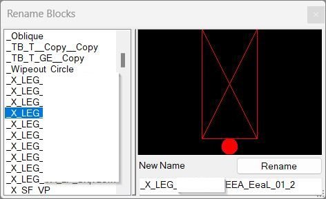
RenameBlockPreview
RenameBlockPreview provides a dialog-based block rename workflow for AutoCAD drawings. The command RenBlocks opens a temporary self-contained DCL interface, lists valid block definitions from the active drawing, lets the user search by partial text, select a block, enter a new name, and apply the rename safely.
The tool is designed for CAD users who manage large drawings with many reusable blocks and need a faster alternative to manual block-table inspection. It filters out anonymous blocks, xref-nested blocks, Model Space, and Paper Space records so the list focuses on real rename candidates.
The routine includes a duplicate-name guard before writing the new block name. If another block definition already uses the requested name, the rename is blocked and the user is asked to choose a different name.
RenameBlock
🧱 RenameBlock is a compact AutoLISP utility for renaming the block definition behind a selected block reference in the active drawing.
🔍 The user selects a block reference, and the routine reads the real block name or EffectiveName when the selected object is a dynamic block.
📝 A text editor prompt is opened with the current block name, allowing the user to type a new valid block name while avoiding duplicate block names.
🔒 Xrefs are excluded because the routine checks the block table record and does not process external references.
↩️ The operation is wrapped in an AutoCAD undo mark and temporarily suppresses command echo while running the internal RENAME command.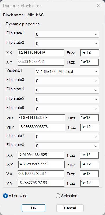
DynamicBlockFilter
📘 DynamicBlockFilter scans AutoCAD dynamic block references and builds a filtered selection set based on dynamic block property values. The user starts by selecting a source
AcDbBlockReferencethat is confirmed as a dynamic block throughvla-get-IsDynamicBlock.
🔍 The routine reads the block effective name withvla-get-EffectiveNameand extracts its dynamic properties throughgetDynamicBlockProperties. It then creates a temporary DCL dialog where the user can choose allowed property values, enter custom values, or leave a field empty to match all values.
🧠 For properties withAllowedValues, the program displays popup lists with an asterisk option for all values. For editable numeric or text properties, it displays edit boxes and optional fuzz tolerance fields, making the tool practical for distance, angle, visibility, lookup, stretch, flip, rotation, and other dynamic block parameters.
📌 The user can search either the entire drawing or a manual selection set. Matching references are selected in AutoCAD usingsssetfirst, so the result can immediately be edited, moved, copied, erased, changed by layer, or used inside another command.
🟧 This AutoLISP tool does not create, modify, or rename Civil 3D alignments, surfaces, sections, profiles, labels, or styles. Its purpose is focused on dynamic block filtering, AutoCAD selection automation, DWG cleanup, block auditing, and Civil 3D drawing management support.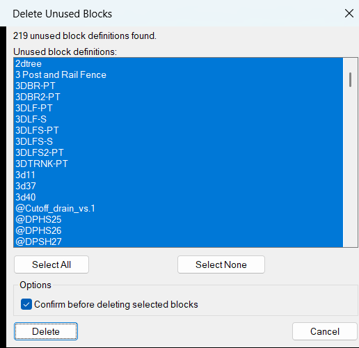
DelUnusedBlocks
📘 DelUnusedBlocks is a practical AutoCAD AutoLISP tool for cleaning unused block definitions from DWG files through a generated DCL interface. The user runs
DelUnusedBlocks, and the program scans the drawing block table for block definitions that can be deleted safely because they are not inserted in the drawing.🔍 The routine uses
tblnexton theBLOCKtable, checks the block flag value from DXF group code70, excludes xrefs, xref-dependent definitions, externally dependent blocks, resolved xrefs, layout blocks, and anonymous/system definitions, then removes any block names that still have matchingINSERTreferences found byssget "_X".🧠 The cleaned list is shown in a multi-select DCL list box. The user can choose all unused blocks, choose none, select individual unused block definitions, and optionally require confirmation before deletion. The selected block definitions are then deleted from the drawing database using ActiveX methods such as
vla-itemandvla-delete.💾 The dialog remembers the previous confirmation setting, previous selected block names, and dialog position through
DelUnusedBlocks.cfg. This makes repeated AutoCAD cleanup sessions faster and more consistent.🔴 Important: this utility deletes unused block definitions from the DWG block table. It does not delete placed block references because inserted blocks are filtered out, but deleting block definitions is still a drawing cleanup action that should be used on a saved or backed-up DWG when required.
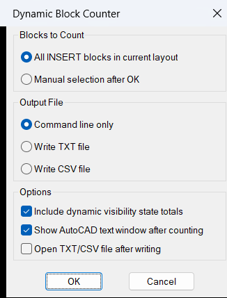
DynamicBlockCounter
📘 DynamicBlockCounter is a practical AutoCAD AutoLISP utility designed to count block references, dynamic block references, and xref-style insert references in the active DWG layout. The tool is useful for CAD managers, Civil 3D designers, BIM coordinators, drafting teams, and production users who need a fast block quantity report without manually inspecting the drawing.
🔍 The workflow is simple: the user runs
DBCOUNT, the program scans the current layout forINSERTentities, and then the user can either select a subset of blocks or count all detected blocks. The routine resolves the effective block name usingLM:blockname, so anonymous dynamic block names are reported by their real visible block name where supported.🧩 For dynamic blocks that contain a visibility parameter, the program does more than count the block name. It reads the visibility parameter name from the block definition extension dictionary and then extracts each selected block reference visibility value through
getdynamicblockproperties. This makes it possible to report totals per visibility state, such as different manhole types, sign types, object variants, symbols, or Civil 3D plan production block configurations.📊 After processing the selection, the routine prints a formatted block count table to the AutoCAD command line and opens the text screen with
textpage. The user may also chooseTXTorCSVexport. The output file is automatically created in the active drawing folder using the current drawing name as the base filename.🧠 This LISP does not modify drawing geometry. It is a reporting and audit tool for AutoCAD and Civil 3D block management, dynamic block quantity extraction, xref reference review, DWG cleanup, symbol counting, visibility-state checking, and CAD production quality control.
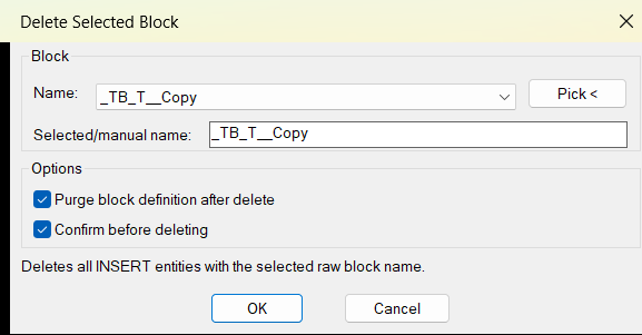
DelSelectBlock
📘 DelSelectBlock scans the active AutoCAD drawing for block references and builds a dialog-based list of available raw block names. The user can select a block name, type a manual name, or pick a block reference directly from model space or paper space.
🔍 After the user confirms the operation, the program finds every
INSERTentity whose raw block name matches the selected value. It then deletes those block references using ActiveXvla-delete.🧹 The tool is useful for AutoCAD drafting cleanup, repeated symbol removal, DWG block management, drawing simplification, and fast removal of unwanted block instances across the entire drawing.
🔐 The dialog saves the last block name, confirmation setting, purge setting, block history, and dialog position in
DelSelectBlock.cfg. The configuration file is written toROAMABLEROOTPREFIX, the drawing folder, or the temporary folder depending on what AutoCAD paths are available.Important: this command is destructive. It deletes all matching block references in the drawing. Use the confirmation option and standard AutoCAD undo carefully.
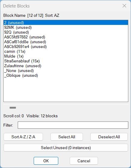
DeleteBlocks
📘 DeleteBlocks scans the active AutoCAD drawing and builds a list of block definitions with their detected instance counts.
The user startsDELBLOCKS, reviews the generated dialog, filters block names, changes sort direction, selects one or more block definitions, and confirms deletion.
The program then removes matching block references from model space, paper space, and block definitions where possible, and attempts to delete the selected block definitions from the drawing database.
The dialog includes practical productivity features such as persistent filter text, remembered dialog size, horizontal list scrolling, visible item counts, A-Z or Z-A sorting, select all, deselect all, and a button to select zero-instance blocks for cleanup.
This AutoCAD block cleanup utility is useful for CAD managers, Civil 3D production teams, drafting technicians, and BIM or CAD coordinators who need to remove unused or unwanted block definitions from large DWG files.
Important: this is a destructive cleanup command because selected block names are deleted globally from the current drawing where the AutoCAD database allows deletion.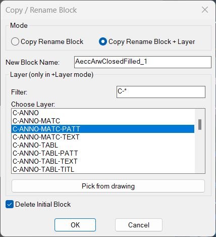
CopyBlock
• Block picking: Prompts you to pick a block reference and verifies that it is an INSERT and not on a locked layer before continuing. • Default naming: Proposes a default new block name based on the original name (Base_1, Base_2, and so on) that is guaranteed to be unique among existing blocks. • Dialog modes: The dialog offers two modes via radio buttons: “Copy Rename Block” and “Copy Rename Block + Layer”. • Name input: Allows you to type a custom new block name and validates it against existing block names and symbol name rules. • Layer tools (+Layer mode): When the “Copy Rename Block + Layer” mode is active, a layer filter box, a layer list, and a “Pick from drawing” button become active so you can choose a target layer interactively. • Delete toggle: A “Delete Initial Block” toggle (default on) controls whether the original reference is deleted after the new, renamed copy is created and retargeted. • Definition cloning: Uses ObjectDBX to copy the original block definition to a temporary database, rename it there, and copy the renamed definition back into the active drawing as a new block. • Reference handling: Keeps a handle to the original reference, and in copy mode creates a duplicate reference, then repoints the active (possibly copied) reference to the newly created block definition. • Layer enforcement (+Layer mode): If a layer is chosen, sets the new block reference to that layer and optionally forces all geometry inside the new block definition to that layer and ByLayer properties. • Original cleanup: If the “Delete Initial Block” option is enabled, the original reference is deleted, leaving only the new renamed (and possibly re-layered) reference in place. • Error and cancel: Handles invalid names, ObjectDBX failures, and user cancellation with informative messages and clean exit.ChangeBlockEntitiesLayer
• Block selection: Prompts the user to select only INSERT entities which represent block references in the drawing. • Reference analysis: For each selected block reference, reads its block name and its current layer name. • Definition lookup: Locates the corresponding block definition in the active document Blocks collection by using the block name. • Entity iteration: Loops through every entity that belongs to the block definition and checks whether it has a Layer property. • Layer matching: Compares each entity layer with the block reference layer and, when they differ, updates the entity to use the same layer as the reference. • Feedback: After processing all selected blocks, prints a confirmation message that entities inside the selected blocks have been updated. • No selection case: If no block references are selected, displays a notice that no block references were selected and performs no changes.3D_PolyOffset
- Saves current system variables (OSMODE, PLINETYPE, VIEWDIR).
- Switches to World UCS and disables object snaps.
- Extracts all vertex coordinates from the selected 3D polyline.
- Generates a temporary 2D polyline using XY coordinates only (Z set to 0).
- Offsets the temporary 2D polyline by a specified distance.
- Reads offset vertex coordinates.
- Creates a new 3D polyline by combining offset XY values with original Z values.
- Deletes temporary 2D polylines.
- Restores original system settings.
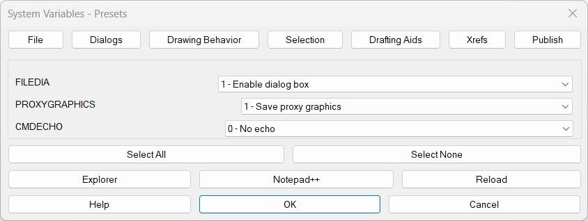
SteSysVar
🚀 SteSysVar is a dialog-driven AutoCAD and Civil 3D system variable manager designed for CAD users who need a fast, repeatable way to tune drawing environment settings.
📂 The tool organizes important AutoCAD system variables into clear tabs: File, Dialogs, Drawing Behavior, Selection, Drafting Aids, Xrefs, Publish, and Layer Tools. Each tab uses dropdown controls instead of raw numeric input, so values such as FILEDIA, ORTHOMODE, PICKFIRST, OSMODE, DYNMODE, XREFOVERRIDE, PUBLISHCOLLATE, and LAYERISOLATION can be reviewed and applied with readable labels.
🧠 SteSysVar improves CAD productivity by reducing manual SETVAR work, documenting recommended defaults, grouping related variables, and giving the user quick access to help text, source reload, folder opening, and Notepad++ editing from the same interface.
🟡 Tags: 🏷️ AutoCAD, 🏷️ AutoLISP, 🏷️ Civil 3D, 🏷️ System Variables, 🏷️ CAD Environment, 🏷️ Drafting Settings, 🏷️ Selection Settings, 🏷️ Xref Settings, 🏷️ Publish Settings, 🏷️ Layer Isolation, 🏷️ DCL Dialog, 🏷️ Productivity Tool

Hide / Show Objects
When executed, the program: • Step 1 Writes a temporary DCL file defining a simple dialog with three radio buttons and OK/Cancel controls. • Step 2 Opens the dialog and preselects the last used option (default “Isolate the selected”). • Step 3 Captures which option the user selects and runs the matching visibility function: – “Isolate the selected” → hides everything else. – “Hide selected” → hides only the chosen objects. – “Display all” → shows every hidden object again. • Step 4 Redraws the view after the visibility change. • Step 5 Restores the previous choice as default for next run.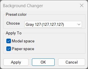
Change Background Color
When executed, the program: • Step 1 Loads AutoCAD’s display and drafting preferences and builds a list of predefined gray/black/white color options. • Step 2 Displays a dialog with a dropdown list of color presets and toggles for Model and Paper space. • Step 3 Applies the selected color to the chosen workspace(s), adjusting crosshair, tracking, and snap marker colors for contrast. • Step 4 If Cancel is pressed, restores the previous colors using a saved snapshot.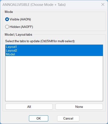
AnnoAllOnOff
🔇 AnnoAllOff is an SEO-friendly AutoCAD annotation visibility control tool for managing annotative object display across Model Space and Paper Space layouts.
🧩 The routine dynamically writes a temporary DCL file, lists all layout tab names from the active drawing, selects all tabs by default, and lets the user choose All, None, or a custom multi-selection.
📐 For each selected tab, the command switches CTAB to that tab, forces Paper Space when required, runs ANNOALLVISIBLE 0, and then restores the previous CTAB, TILEMODE, and MSPACE state.
📌 This is useful for AutoCAD and Civil 3D production drawings where annotative objects, labels, text, dimensions, and multileaders need controlled visibility per tab before review, plotting, or cleanup.
🧠 The script notes that ANNOALLVISIBLE is stored per Model tab and per Layout tab, not per viewport entity.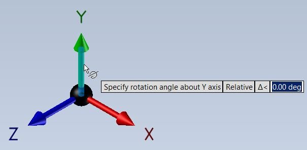
RotateUCS
When executed, the program does the following: • Sets the UCS to World using (command “_UCS” “_W”) so the rotation always starts from a known base. • Resets the snap angle to 0 using (command “_snapang” 0) so the cursor/ortho aligns with the new UCS properly. • Prompts the user: “Specify rotation angle:” and reads the angle in radians (AutoCAD default). • Converts the angle from radians to degrees with (* angle (/ 180 pi)) because the UCS command expects degrees. • Calls (command “_UCS” “_Z” ang1) to rotate the UCS around the Z axis by the specified angle. • Prints a confirmation message like “Angle of UCS: 45.00” using (princ …) and (rtos …) for formatting. • Finally asks the user for a UCS name and, if provided, saves the UCS with (command “_UCS” “_Save” ucsname).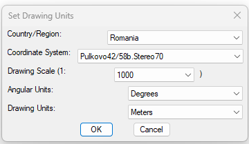
SetUpUnits
📘 SetUpUnits is an SEO-friendly Civil 3D AutoLISP command that centralizes drawing unit setup, coordinate system selection, and drawing scale configuration in a generated DCL dialog.
🌍 The routine displays a country or region list, updates the available coordinate system codes for the selected location, and shows a live flag preview beside the selector. This helps Civil 3D users choose coordinate settings more clearly when working with international projects, UTM systems, national grid systems, and local drawing standards.
📐 After the user accepts the dialog, the program connects to the Civil 3D Land application object and writes the selected settings into the active drawing’s unit zone settings. It updates the Civil 3D coordinate system code, drawing scale, angular units, and drawing units through Aecc COM automation.
🚩 The flag preview is loaded on demand from external country flag data files. RGB pixel values are mapped to AutoCAD ACI colors and drawn into the DCL image tile using optimized run-length fill_image calls.
🧭 This tool is useful for CAD managers, Civil 3D designers, survey teams, roadway engineers, infrastructure projects, template maintenance, and drawing setup workflows where coordinate systems and units must be applied consistently.
C3D_NamespaceFix
🧩 C3D_NamespaceFix is intended to diagnose AutoLISP namespace problems that can affect core arithmetic operators and Visual LISP COM functions in AutoCAD or Civil 3D.
🔎 The routine first evaluates the multiplication symbol and checks whether its type is SUBR.
⚙️ If the multiplication symbol is not a SUBR the routine calls vl-load-com and performs the same check again for a second recovery attempt.
📊 After this attempt the file prints the detected types of the multiplication addition subtraction and division symbols.
🧪 It safely tests multiplication through vl-catch-all-apply and reports the result of multiplying 3 by 7.
🔌 It also tests access to the AutoCAD COM object through vlax-get-acad-object and reports whether that protected call produced an error.
🧠 Finally it checks whether vl-load-com exists in the AutoLISP atom table.LayerFilterFreezeThaw
❄️ LayerFilterFreezeThaw is an SEO-friendly AutoCAD layer filter action tool for applying layer state changes to predefined layer groups.
🧱 The DCL dialog presents a filter list and radio-button action set, allowing the user to freeze, thaw, turn on, turn off, lock, or unlock matching layers.
🚆 The Kable filter contains 30 exact layer names for Hartingstecker, 30 kV K1 and K2, OSE, Ortsnetz, and 750 V layer groups, making the routine highly targeted for repeated project standards.
🔁 The invert option applies the chosen action to all layers except the selected filter, supporting quick isolation workflows.
📌 This is useful for Civil 3D production drawings, railway electrical layers, project layer visibility control, quick cable-layer isolation, and CAD layer cleanup.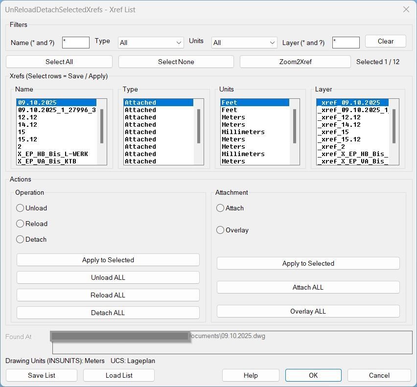
UnReloadDetachSelectedXrefs_00
Description:- Core concept: The tool treats the Xref setup as a reusable “profile” stored in a text list file and re-applies it deterministically.
- Displayed data: Xref Name, Type (Attached/Overlay), Units (abbrev), Layer, and resolved Found At path preview for the active row.
- Safety behavior: “ALL” operations are wrapped so the user’s UCS and view are restored after execution, preventing unwanted zoom/UCS side-effects.
- Deterministic load workflow: When applying a list, each xref is processed one-at-a-time with a fixed UCS/units sequence to avoid scaling mismatches.
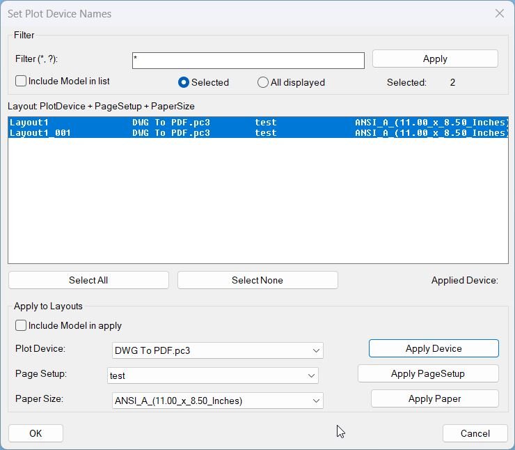
SetPlotDeviceNames_00
- Loads COM and targets a single plot configuration name: DWG To PDF.pc3.
- Gets the active document and its Layouts collection, then loops through each layout.
- For each layout, refreshes plot device information, retrieves the list of available plot devices, and checks whether the target device exists.
- If available, sets the layout’s ConfigName to the target device; otherwise, prints a message naming the layout that lacks the device.
ConvertPolylineAndText2Mleader
📘 ConvertPolylineAndText2Mleader is an AutoLISP drafting utility for AutoCAD users who need to convert selected POLYLINE or LWPOLYLINE geometry into leader-style annotation paths. The implemented command is P2L. It asks the user to select polyline objects, reads each vertex with Visual LISP curve functions, starts the AutoCAD LEADER command, places leader vertices from the original polyline path, applies MATCHPROP from the original polyline to the newly created leader, and deletes the original polyline. This makes it useful for drawing cleanup, annotation conversion, polyline-to-leader drafting workflows, and CAD production tasks where existing linework needs to become leader annotation geometry.
CopyPaste2BasePoint
📐 CopyPaste2BasePoint streamlines a common CAD coordination workflow: copying geometry from one drawing and pasting it into another drawing while preserving the same origin reference.
🧭 Instead of manually choosing a base point each time, the routine uses the fixed coordinate 0,0,0 for both COPYBASE and PASTECLIP operations.
🔄 This is useful for AutoCAD, Civil 3D, and infrastructure drafting workflows where xrefs, base drawings, layouts, design references, or copied model geometry must stay aligned by drawing origin.
🛡️ Before running the copy or paste command, the program temporarily disables object snaps and command echo settings to reduce accidental snap interference.
🔁 After the operation, it restores OSMODE, CMDECHO, optional 3DOSMODE, and optional AECBOSMODE values so the user’s drafting environment is returned to its previous state.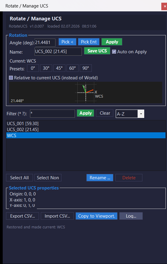
RotateUcs_vs.01
🧠 RotateUcsCs is a C# .NET port of a RotateUCS AutoLISP DCL workflow. Instead of using a DCL dialog and command-line sequencing, the project provides a modeless WinForms palette that uses AutoCAD managed APIs to rotate, save, restore, rename, delete, export, import, and preview named UCS records.
The main user workflow starts withROTATEUCSorRUCS. The palette lets the user type a rotation angle, use preset angle buttons, pick an angle from the drawing, or pick an entity and extract its natural angle. The plugin supports entity angle extraction from AutoCAD geometry such asLine,Polyline,Polyline2d,Polyline3d,Arc,Xline,Ray, andSpline.
The tool can save the current UCS as a named UCS using automatic naming such asUCS_001 [45.00]. It can also restore named UCS records, rename existing UCS definitions, delete selected named UCS records, filter the UCS list with wildcard patterns, sort by several modes, and display origin and axis information for the selected UCS.
The palette also includes workflow features that are useful for Civil 3D and AutoCAD production drafting: a live 2D UCS preview, transient viewport UCS highlighting, CSV export and import for named UCS definitions, copy-to-layout-viewport support, persistent registry settings, a dark CAD-style UI theme, and a detachable log window. Although it can run inside Civil 3D, the plugin manages AutoCAD UCS and viewport behavior only. It does not directly modifyProfileView,SectionView,Alignment, corridors, surfaces, labels, bands, pipe networks, point groups, or Civil 3D styles.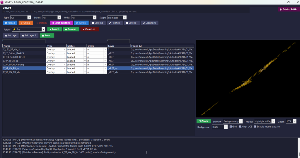
UnReloadDetachSelectedXrefs_vs.02
📘 This project is a C# .NET plugin for AutoCAD and Civil 3D that focuses on external reference management. After the user loadsXRNET.dlland runsXRNET, the tool scans the active DWG and collects detected DWG xrefs and raster image references.
🔍 The program displays the reference name, xref type, load status, drawing units, layer, and source file path in a practical WinForms grid. This allows the user to quickly understand which external references are loaded, unloaded, missing, attached, overlaid, raster-based, or path-related.
🧠 The user can select one or multiple references, filter the list, inspect file paths, preview selected geometry, reload references, unload references, detach references, set xref layers, save reference lists, repair paths, export CSV data, and generate diagnostic logs.
📊 TheXRSPLITcommand opens a dedicated xref splitter workflow. This tool can load xref list TXT files, import references from the current drawing, validate missing paths, scan folders for matching DWG files, merge list files, export selected rows, generate xref layer names, create abbreviations, re-path entries, reorder rows, and apply selected xref records back to the active DWG.
📌 Important code note: this plugin does not edit Civil 3DProfileView,SectionView,Alignment, bands, labels, or Civil 3D styles. Its actual purpose is AutoCAD and Civil 3D xref management, raster reference management, DWG dependency cleanup, preview, export, and path validation.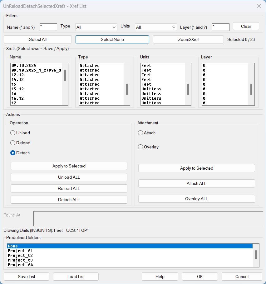
UnReloadDetachSelectedXrefs_01
Description This lisp scans the current drawing for xref definitions and displays them in a multi-column dialog (Name, Type, Units, Layer) with synchronized selection across columns. It allows users to apply batch xref operations, change xref attachment type, and save or load xref lists for repeatable setups across drawings. Predefined folder behavior The Save List and Load List file dialogs can start in a predefined folder chosen from a scrolling list. The predefined folder root is the user OneDrive location and the selected entry appends a relative path such as \Work\Project_01\_extra\Xref_Load_List. The predefined folder options are: None, Project_01, Project_02, Project_03, Project_04, Project_05.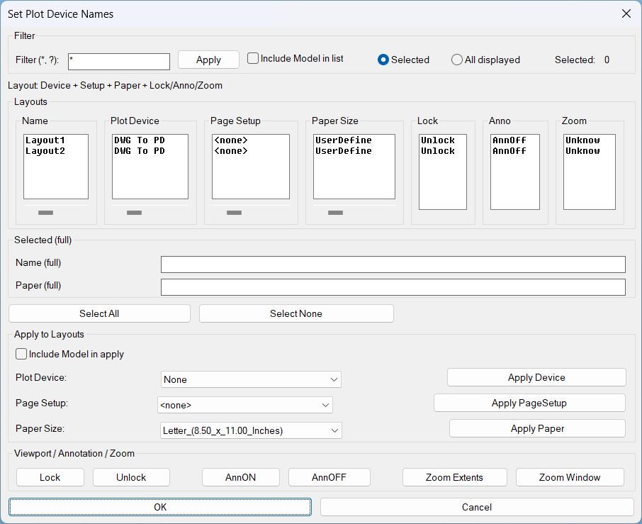
SetPublishLocation_01
Description- Displays layouts in synchronized columns: Name, Plot Device, Page Setup, Paper Size, Lock, Anno, Zoom.
- Supports wildcard filtering and scope control: Selected or All displayed, with optional inclusion of Model in list and apply actions.
- Provides per-column horizontal scrolling for the main text columns using sliders that shift the visible substring left or right without changing stored values.
- Shows full values for the first selected layout in the Selected full area: Name full and Paper full.
- Performs safe context switching when needed by temporarily controlling TILEMODE, CTAB, and MSPACE, then restoring the prior state to avoid disrupting the user environment.
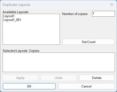
DuplicateLayouts_01
What the user does- Run DuplicateLayouts to open the DCL dialog.
- Select a layout in Available Layouts and enter Number of copies.
- Press Set Count to add or update that layout in Selected Layouts and Copies summary.
- Press Apply to duplicate and keep the dialog open, or press OK to duplicate and exit.
- Press Undo to undo the last session operation, then continue working in the dialog.
- Press Delete to remove an item from the summary when a summary row is selected, otherwise delete the selected available layout tab from the drawing.
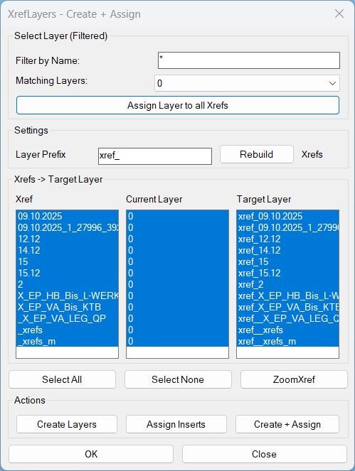
CreatesXrefsLayersAssign_01
Main Purpose- Scans the drawing and lists all XREF block definitions found in the Blocks table.
- Displays three synchronized columns: Xref, Current Layer, and Target Layer (built from the Layer Prefix).
- Provides two assignment modes: per-XREF target assignment and assign one layer to all XREFs via a filtered layer selector.
- Includes ZoomXref to zoom the view to the selected XREF inserts bounding box in Model Space using ActiveX ZoomWindow.
- Option 1: Choose an existing layer from the filtered list and click Assign Layer to all Xrefs.
- Option 2: Set Layer Prefix, then use Create Layers, Assign Inserts, or Create + Assign for per-XREF management.
- Use ZoomXref to zoom to the first selected XREF in the list.
- Press OK or Close to exit (no extra actions on OK).
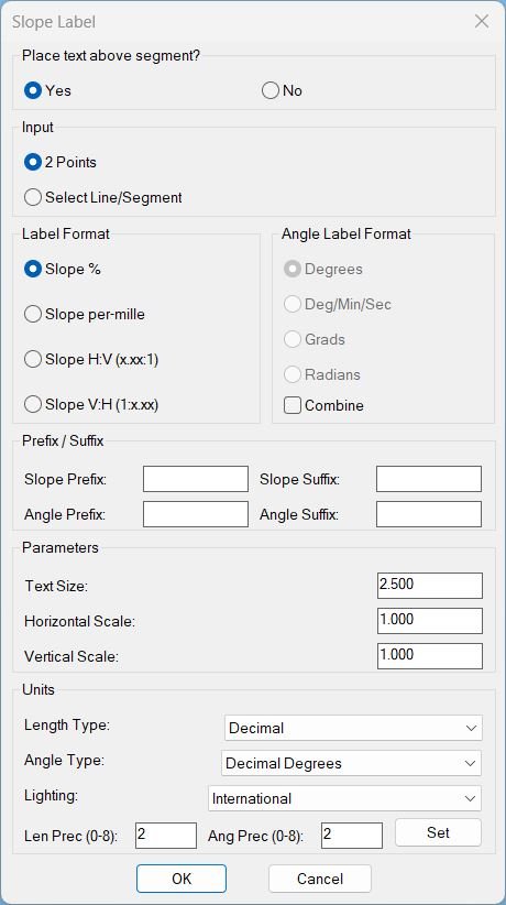
Slope_01
What this command does: Opens a “Slope Label” dialog where you define label style (slope format, angle format, text size, horizontal/vertical scale, prefixes/suffixes, units). After confirming, you choose between two workflows: • 2 Points mode: Repeatedly pick point pairs; each pair gets a slope (and optional angle) MTEXT label at the midpoint, offset above/below the segment. • Select Line/Segment mode: Select one or many LINE/LWPOLYLINE/POLYLINE entities; every individual segment gets a label.Slope_00
This routine provides a configurable slope-labeling tool for AutoCAD drawings, allowing the user to specify labeling format, measurement precision, vertical & horizontal scaling, and position offset before placing slope annotations. After configuration, the user selects two points representing the measurement line. The routine computes run and rise, detects slope direction, applies the chosen formatting rules, and places a TEXT entity at a controlled position relative to the middle of the picked segment. The process can be repeated by running the command again with the same or modified dialog settings.CloseParalelPolylines
This routine takes exactly two valid open curve objects, forces polylines open if closed, connects their start points and end points using new LINE entities, then merges everything into one polyline using PEDIT join. System prompts are suppressed and restored afterward for clean automated processing.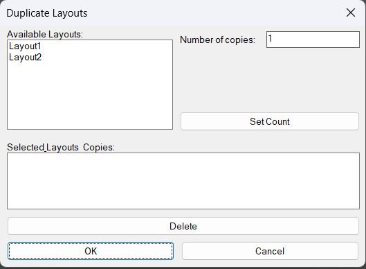
DuplicateLayouts_00
- Creates a temporary DCL file at runtime and opens a dialog listing available layouts (excluding Model).
- Allows the user to assign a Number of copies to the currently highlighted layout using Set Count, building an internal map of LayoutName → CopyCount.
- Shows the chosen layouts and counts in a summary list; the user can remove entries via Delete prior to execution.
- On OK, duplicates each selected layout the requested number of times by calling ._layout _copy and naming copies with an incremented numeric suffix (e.g., Layout_01, Layout_02).
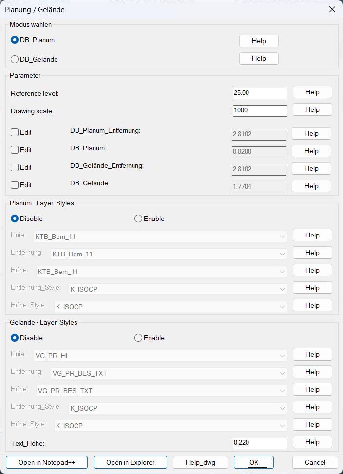
DB_Planung_Gelände
• Defaults and globals: Initializes default mode, reference level, drawing scale, offsets for Planum and Gelaende labels, layer names, text styles, text height, and flags for which fields can be edited or which style popups are enabled. • Help file mapping: Stores file names for help images and a sample DWG, and resolves them via support paths, LSP folder, and DWG folder so that context sensitive Help buttons can open the correct reference graphics. • Dialog writer: Dynamically writes a DCL file defining the “Planung / Gelaende” dialog with radio buttons for mode, parameter edit boxes, offset toggles, Planum and Gelaende layer and style popups, text height control, and bottom buttons for Notepad plus plus, Explorer, and help DWG. • Parameter editing: The dialog allows editing of reference level, drawing scale, four offsets (Planum distance and elevation, Gelaende distance and elevation), and main text height, with edit toggles that gray or enable individual numeric fields. • Layer and style selection: Builds sorted lists of all drawing layers and text styles, merges them with pre defined defaults, and exposes them as popup lists for Planum and Gelaende line, distance, and elevation layers and styles, with separate enable or disable radio controls per group. • INI persistence: Reads and writes an INI file in the drawing folder (ScTrMoss.ini), storing mode, numeric parameters, layer and style selections, edit toggles, and enable style flags so the dialog remembers the previous configuration between sessions. • Planum drawing routine: The C:DB_Planum command asks for the intersection point between center line and band, finds cartridge and profile reference lines, sets up temporary layers for visual guidance, then repeatedly asks for quotation points and places leader lines plus Planum distance and elevation texts using Planum offsets and layers. • Gelaende drawing routine: The C:DB_Gelaende command performs a similar workflow but uses the Gelaende offsets, layers, and styles, placing ground profile distance and elevation texts relative to the same reference point and band geometry. • Numeric calculations: For each picked quotation point it computes the horizontal distance and vertical delta from the intersection point, scales them by drawing scale, adds the reference level to vertical difference to get elevation, and formats both values as text with configured precision. • System state management: Both Planum and Gelaende routines store and restore osmode, clayer, ucsview, dimzin, expert settings, and view “orig” state, optionally wrap operations in an undo group, and clean up temporary color changes to guiding layers. • Launcher flow: The DB_P_G launcher runs the dialog, processes the user choice and settings, writes the INI if accepted, then calls either Planum or Gelaende routine; on cancel it prints a simple cancel message and exits cleanly.
CubeDisplay_Off_On
When executed, the program performs the following actions: • Loads the COM interface using (vl-load-com) to access the AutoCAD ActiveX API. • Retrieves the active drawing document object using (vla-get-activedocument (vlax-get-acad-object)). • Sends the AutoCAD command NAVVCUBEDISPLAY 1 to temporarily disable the Navigation Cube. • Immediately sends NAVVCUBEDISPLAY 3 to re-enable and refresh the cube display, ensuring it becomes visible and properly updated. • Finishes silently using (princ) to avoid leaving residual command line messages.