
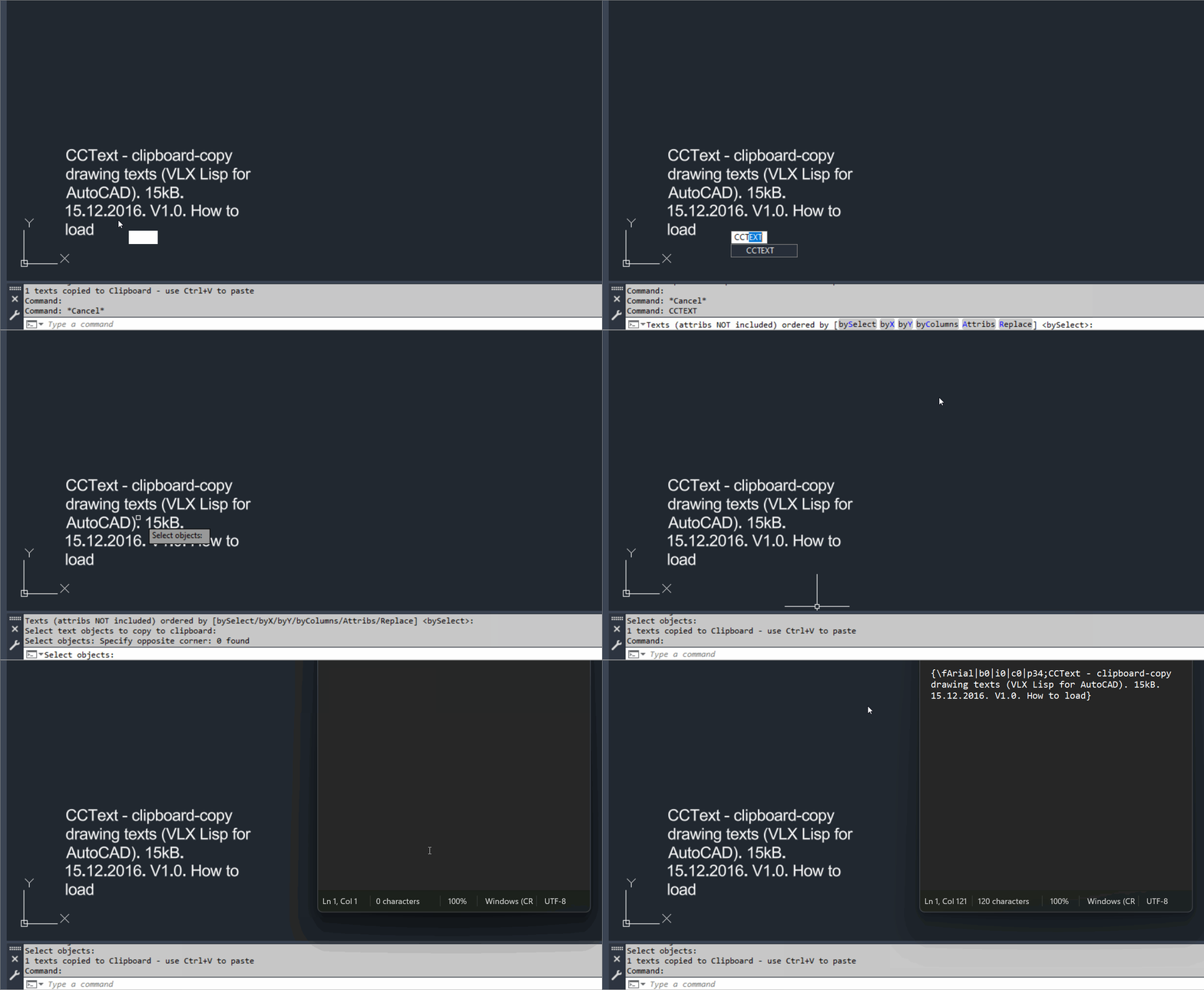
CopyClipboardText
🎯 The result is ordered plain drawing text content placed on the Windows Clipboard for use in Word spreadsheets editors or other Windows applications.
Spline2Poly
🎯 The result is polyline geometry converted from selected or all valid SPLINE entities using SPLINEDIT precision 1.
Slope_Ro
🎯 The current result is an alert containing the simplified Slope_Ro ratio and slope angle in degrees.
SelectStraightEntities
🎯 The result is an active selection containing orthogonal line and polyline geometry from the current layout except objects on PAGE_LIMIT_02.
ParallelPolylinesOption
🎯 Close mode produces one joined polyline from two parallel sides and two end connectors.
↔️ Unclose mode produces two open lightweight polyline sides from a suitable closed polyline.
➗ An optional centerline can be generated in either workflow.PLTools
🎯 The result depends on the selected command and can include edited vertices joined polylines reversed geometry converted 2D or 3D polylines segment reports and generated middle or rectangular polyline geometry.
🧰 PLTools acts as a consolidated maintenance and geometry editing toolkit for heavy polyline workflows.OffsetAndLayer
🎯 The result is offset curve geometry on the selected destination layer.
↔️ The routine attempts to ensure the resulting offset direction matches the requested Inward or Outward choice.MultiOffsetBothSidesWithLayer
🎯 The result is a structured set of parallel offset geometry based on the selected engineering profile and object interpretation.
📐 Depending on options the output can include duct boundaries extra offsets one closed outer polyline helper centerlines and target layer assignment.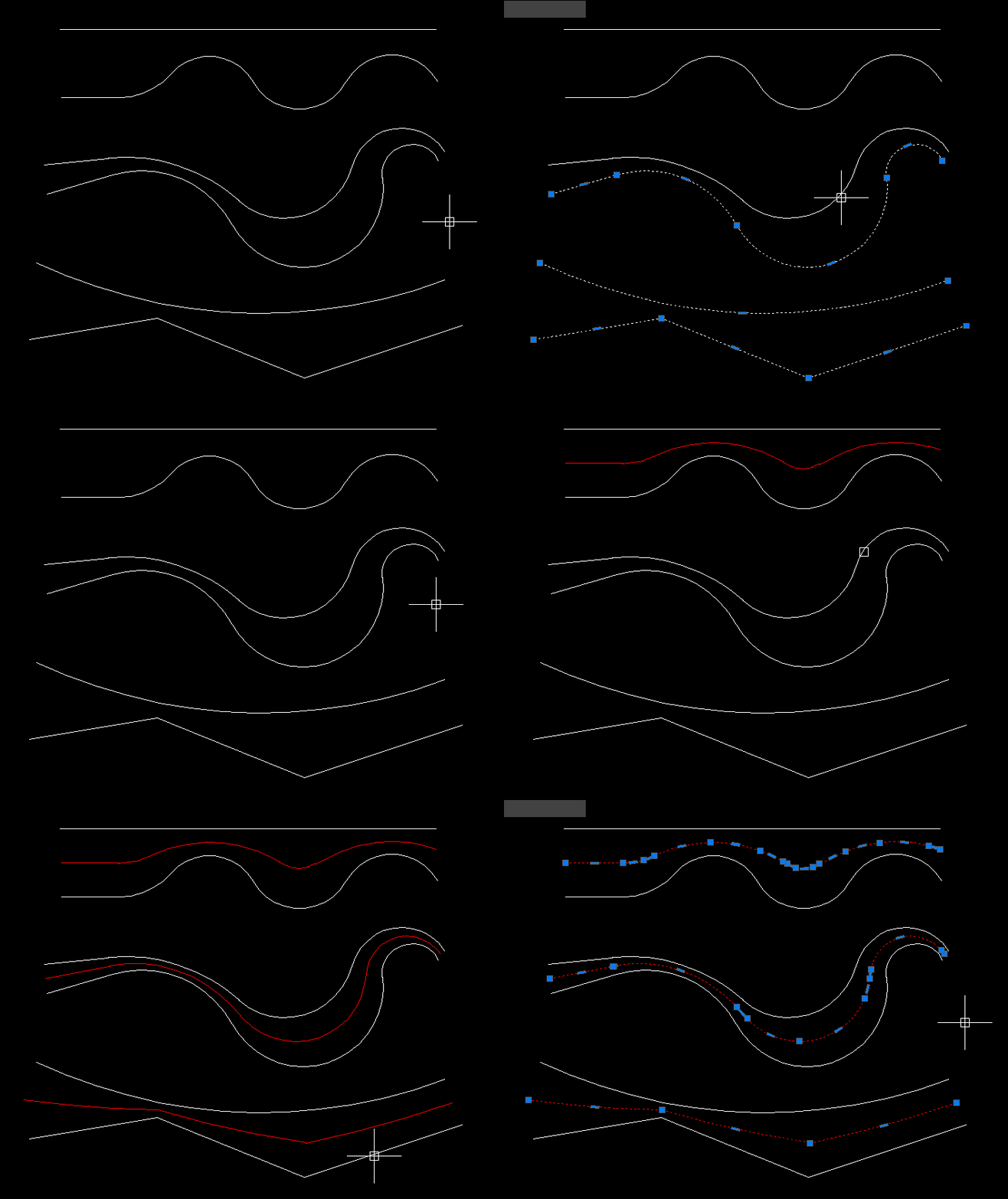
MiddleLinePolylines_2
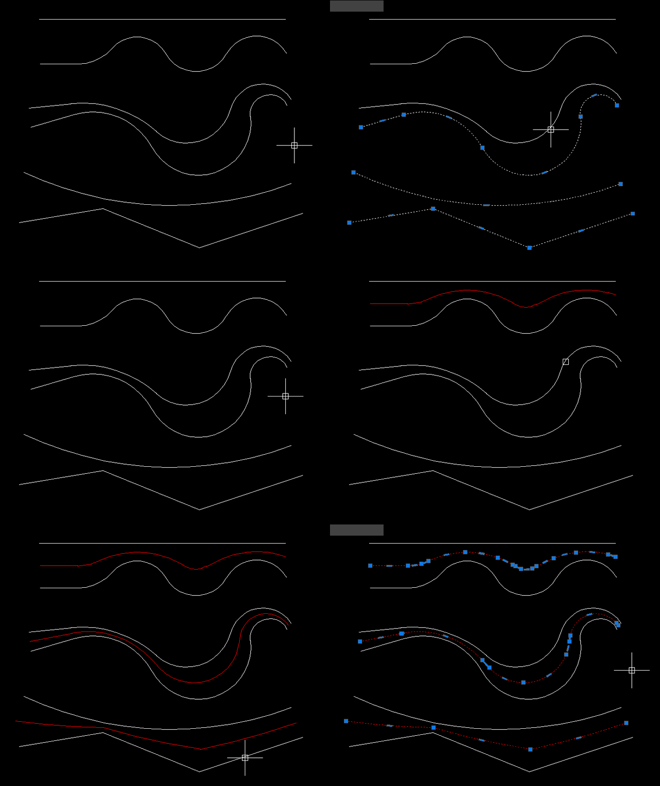
🎯 The result is one straight two vertex LWPOLYLINE centered between the start and end positions of the first and last selected source curves.
MiddleLinePolylines
🎯 The result is a centerline between the two selected open curves.
📐 The resulting entity can be a polyline for straight source geometry or a spline when curved geometry requires it.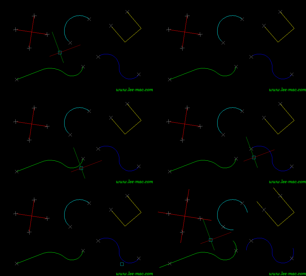
Lengthen
🎯 The result is selected curve geometry extended at the start end or both ends according to the current DCL settings.
👁️ The interactive preview and rollback workflow is designed for rapid trial and adjustment.InteriorPolylinesArea
🎯 The result can be broken curve networks closed boundary regions lightweight polylines cleaned closed areas or a unioned area outline depending on the selected option.
🗺️ The suite is suited to catchment parcel and enclosed area preprocessing.ExtendStartEndMultiple
🎯 The result is the original selected curve geometry lengthened independently at its start and end.
🔄 The command supports iterative adjustment before the user accepts the final state.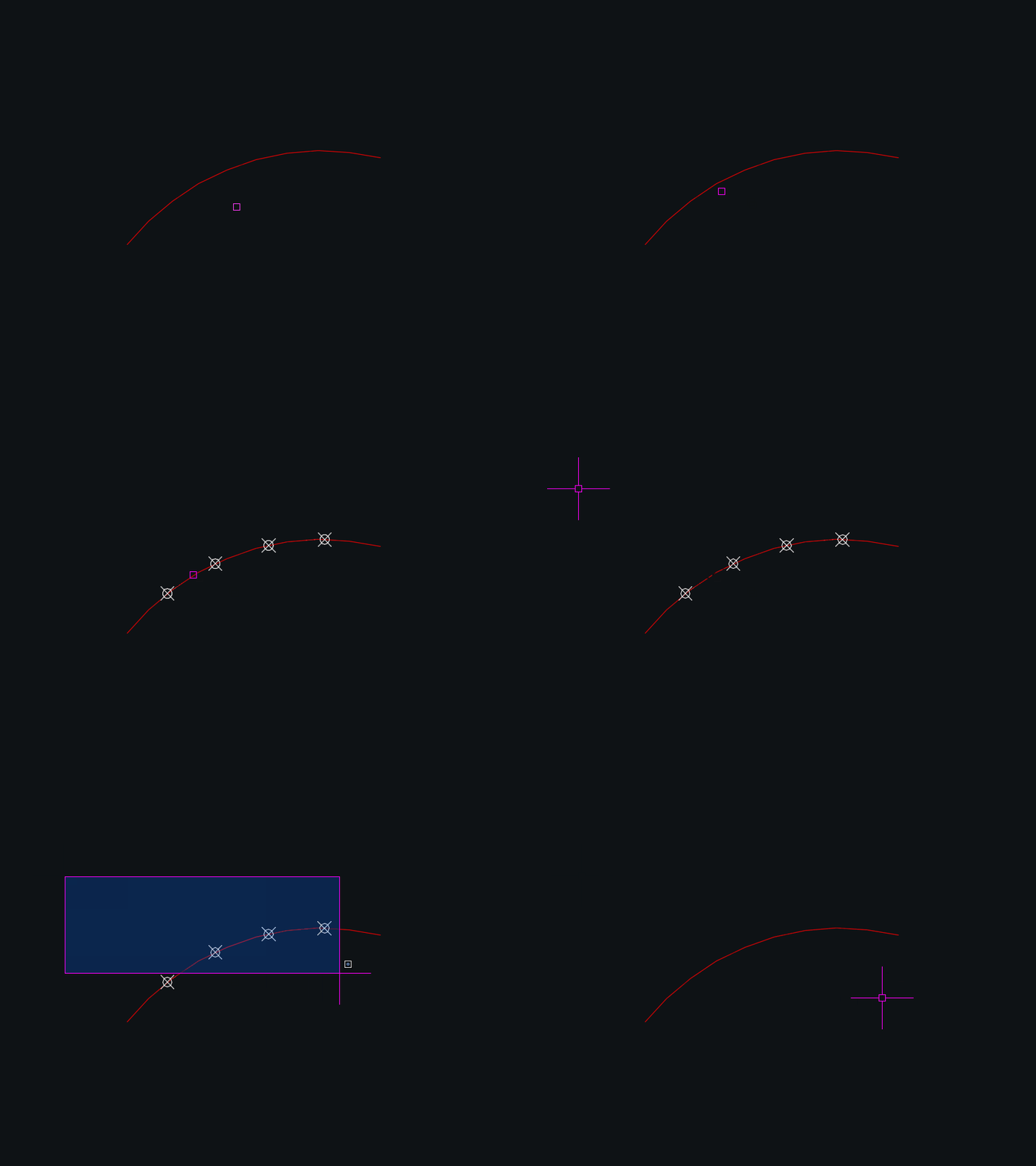
DynamicDivide
🎯 The result is a set of AutoCAD POINT entities positioned at equal intervals along the selected curve.
📏 The source curve remains unchanged.DuplicateToNewLayer
🎯 The result is a pair of left and right offset entities for every selected source curve.
🔗 In Close mode a valid one plus one offset pair is connected and joined into closed parallel geometry.
➗ When enabled an additional sampled centerline lightweight polyline is generated between the two offsets.DoubleOffset
🎯 The result is a matched pair of offset curves located on opposite sides of the selected source entity.
🧰 The tool is useful for rapidly generating parallel boundaries center based corridor limits utility envelopes and similar two sided CAD geometry.ConvertMultiplePolylines
🎯 The result is a cleaned and modernized polyline set containing lightweight polyline geometry produced from compatible LINE and old 2D POLYLINE entities.
🔗 When joining is enabled compatible objects are also joined through PEDIT using the selected fuzz tolerance and Extend jointype.
🧰 The routine is useful for preparing legacy or fragmented CAD geometry for editing cleanup quantity takeoff boundary creation and Civil 3D workflows.LispLoaderExtra
🎯 LispLoaderExtra v1.5.000 provides the described AutoCAD or Civil 3D workflow.
📌 The generated SEO description is based on the supplied source code or project files.LispLoader v1.0.000
🎯 LispLoader v1.0.000 provides the described AutoCAD or Civil 3D workflow.
📌 The generated SEO description is based on the supplied source code or project files.LayoutVPOverrides
✅ Faster viewport override standardization across sheet sets.
✅ More consistent xref layer visibility and plotted appearance in multiple layout tabs.
✅ Reduced repetitive use of VPLAYER on each layout.
✅ Better control of viewport-specific layer freeze/thaw, color, linetype, lineweight, plot style, and transparency settings.Dan_alldlls
🎯 The result is a compact centralized .NET plugin loading workflow for AutoCAD and Civil 3D.
🧰 The routine reduces repeated manual NETLOAD operations for the configured custom tools.
📄 Basic failure reporting makes it easier to identify which configured DLL path requires attention.@Dan_acaddoc
🎯 The result is a centralized and traceable AutoCAD startup environment for a large custom CAD automation library.
📈 Users can load hundreds of productivity tools from one master file while retaining a clear record of which tools loaded successfully and which require maintenance.
🧰 This supports AutoCAD and Civil 3D production environments with extensive custom LISP VLX and .NET tool collections.ViewportMatchOrientation
🎯 The result is a faster way to match viewport orientation in AutoCAD and Civil 3D drawings.
📐 Layout viewports can be aligned to the same rotated view direction without manual angle calculations.
✅ The command improves sheet consistency for plans, profiles, details, and north-oriented viewports.VportsPoly2Rectang
🎯 The result is a controlled viewport cleanup and conversion workflow for AutoCAD and Civil 3D sheet layouts.
🪟 Users can locate problematic polygonal viewports, lock or unlock viewport sets, convert clipping shapes, and standardize sheets more efficiently.
✅ The tool improves paper space QA for drawings with many layouts and mixed viewport types.PlotExtra
🎯 The result is a structured plotting workspace for AutoCAD and Civil 3D that supports preview, logging, project PDF settings, and future plot automation.
🧰 PlotExtra helps replace scattered manual plot setup steps with a single CAD-oriented interface designed for production sheet workflows.
✅ The project is especially useful as a C#/.NET template for custom plot tools, Civil 3D UI styling, and layout preview utilities.PageSetupAllLayouts
🎯 The result is a faster plot device update workflow for AutoCAD and Civil 3D layout tabs.
🖨️ Users can update PC3 configuration names across all paper-space layouts without opening Page Setup Manager for each sheet.
✅ PageSetupAllLayouts supports plotting consistency, PDF output preparation, and office plotter migration tasks.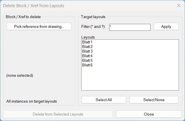
Delete2Layouts
🗑️ Matching block or xref references are removed from the selected paper-space layouts.
📊 The final alert reports how many instances were deleted and from how many layouts.
🧹 The selected block name is passed to PURGE after deletion.
🗂️ The dialog closes cleanly and removes the temporary DCL resources.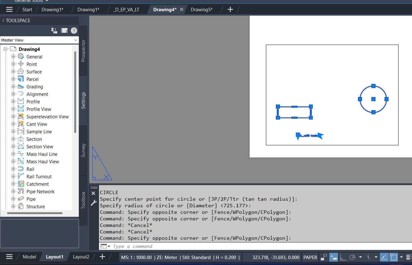
CopyPaper2Model
📤 The selected objects are copied rather than moved, preserving the original entities.
📐 Paper Space copies can be converted into Model Space at the correct viewport scale and location.
🖼️ Model Space copies can be placed into Paper Space viewports for selected layouts.
🔁 The CPMS dispatcher speeds up repeated CAD production work because the same command can be used from different drawing contexts.SelectCreateLayerFilter
🎯 The result is a faster, selection-based layer filter workflow for AutoCAD and Civil 3D drawings.
📌 Instead of manually typing long layer names into the Layer Properties Manager, the user can select representative objects and generate a clean filter expression from their layers.
🧭 This improves layer navigation, xref review, CAD standard checks, discipline-specific filtering, and project drawing cleanup in production environments.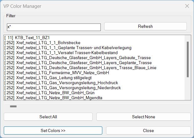
ChangeVPLayerColor
🎯 The result is a faster viewport-color override workflow for AutoCAD and Civil 3D layout sheets.
✅ Users can standardize Paper Space viewport colors for existing utilities, new utilities, xref-derived layers, and project-specific layer naming schemes without manually entering repeated VPLAYER commands.Reconcill_All_Layers
📊 The active DWG no longer stores previous unreconciled-layer baseline records on the processed layers.
🔕 AutoCAD stops showing unreconciled-layer notifications for the current layer evaluation settings.
🧹 The drawing becomes cleaner for production drafting, Civil 3D plan preparation, template reuse, and xref coordination.Make_layers_linetypes_draw
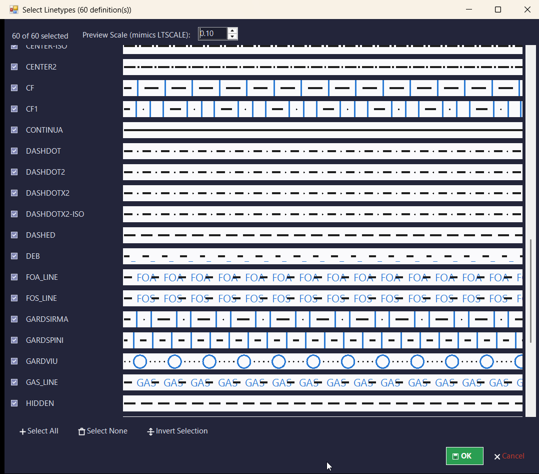
✅ The drawing receives a clean linetype reference sheet made from real loaded linetypes.
✅ Each selected linetype is represented by a sample LWPOLYLINE and MTEXT label.
✅ The output can be used for CAD standards review, plotting checks, linetype libraries, and Civil 3D template documentation.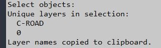
LayersName2Clipboard
✅ A clean newline-separated list of unique selected layer names is copied to the clipboard.
✅ The user can paste the layer list into Excel, TXT files, filters, documentation, or support tickets.LayerImport
✅ Selected layer properties are applied to the current AutoCAD drawing.
✅ Missing layers can be created with imported properties.
✅ Existing layer states can be updated selectively and reversed with the built-in undo snapshot.
✅ A final summary reports created, updated, and skipped layers.LayerFilterFreezeThawOnPlotVPFreeze
🎯 The result is a fast, repeatable layer-filter execution workflow for both model-wide and viewport-specific layer management.
🟢 The tool reduces manual work in the Layer Properties Manager and improves consistency for plotting and layout viewport setup.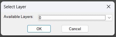
ChangeLayerToSelected_vs.01
🎯 The result is faster and safer layer reassignment with fewer manual Layer dropdown actions.
📋 The optional property-preservation mode keeps object appearance stable while still moving geometry to the selected layer.ChangeLayerToCurrent
🎯 The result is faster and safer layer reassignment with fewer manual Layer dropdown actions.
📋 The optional property-preservation mode keeps object appearance stable while still moving geometry to the selected layer.NamespaceFix
🎯 AutoLISP multiplication expressions continue working after SAVE/QSAVE.
🧩 Tools depending on the built-in * operator are protected against namespace pollution.
🛠️ The CAD environment receives a defensive self-healing startup routine.ChangeBackgroundColor
🎨 The drawing display background is updated for the selected spaces.
👁️ Cursor and drafting marker colors are adjusted to stay visible.
↩️ If the dialog is canceled, the saved color snapshot is restored.
🧹 The temporary DCL file is deleted after the dialog closes.Text2Multileader_2
🎯 The result is a guide-based MLeader conversion workflow where existing linework or temporary polylines become accurate annotation leader geometry.
✅ Text2Multileader_2 is useful for CAD annotation cleanup, conversion of drafted leader sketches, and fast Civil 3D plan-note standardization.SetupOverriteDimStyles
📌 The active drawing workspace can be updated to match the selected object’s layer, text style, text size, dimension style, and MLeader style depending on enabled toggles.
📊 The user sees before/after-relevant counts before accepting the update.
🧹 Temporary DCL files are removed after the dialog closes.MLeaderExtra
The plugin lets CAD users add an extra bend point to MLeader annotation without recreating the leader, improving annotation routing around drawing geometry.
Xline2Poly
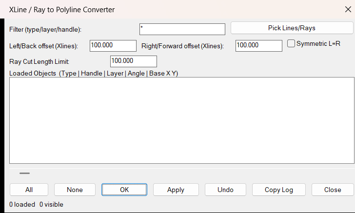
Selected XLINE and RAY objects are replaced by finite LWPOLYLINE segments on the original layer. XLINEs use the configured left/right distances, while RAYs use the configured ray cut length.
Poly2Xline
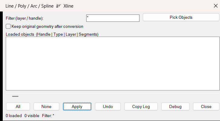
The command creates one or more XLINE construction entities from the selected finite geometry. The output report states how many objects were converted and how many XLINE entities were created.
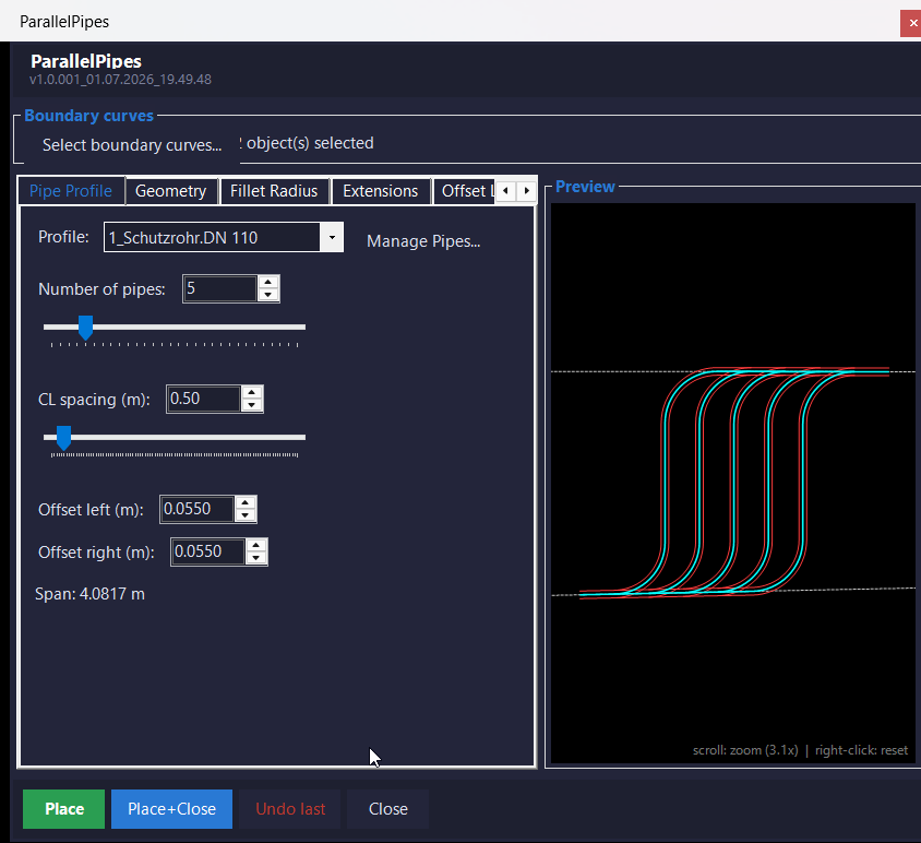
ParallelPipes.NET
The result is a compiled AutoCAD / Civil 3D plug-in project that can be built into ParallelPipesNet.dll and loaded with NETLOAD. Running VTPCS gives the user a visual tool for generating parallel Profile_000 / conduit pipe bundles between selected drawing boundaries. Final placement writes real DWG entities: offset pipe edges, optional centerlines, optional groups, and placement history for fast undo.
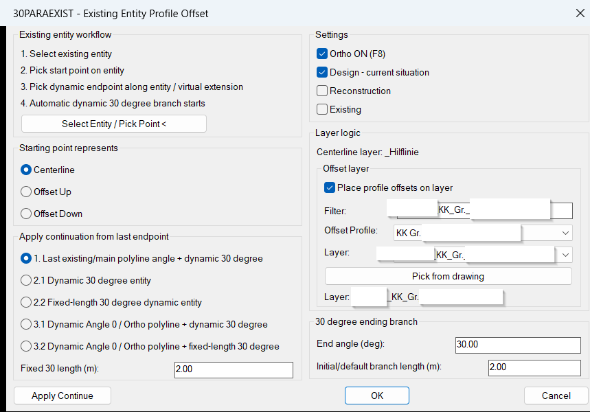
30ParallelExisting
✅ Produces existing-geometry-based utility routes with centerline, offset profiles, branch continuations, and layer logic for Civil 3D and AutoCAD infrastructure design workflows.
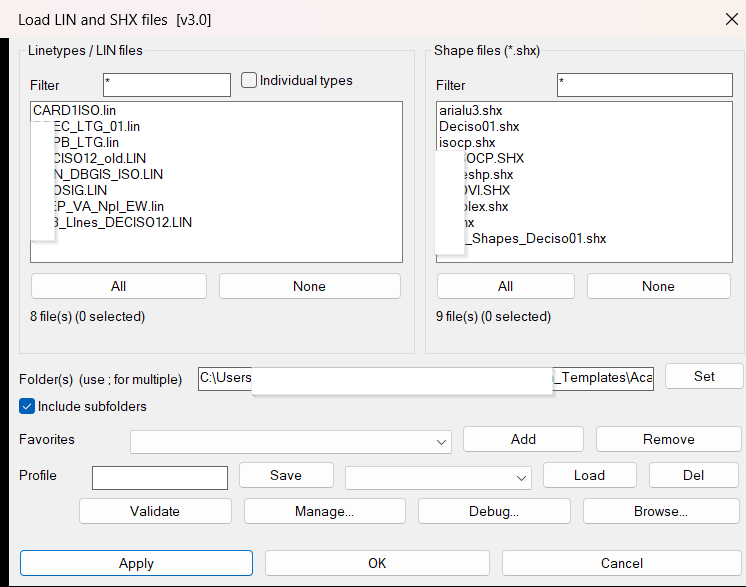
Lin_Shx_Loader
Selected LIN linetypes and SHX shape files are loaded into the active AutoCAD drawing. The command line reports how many LIN and SHX items were loaded and how many errors occurred. Validation and debug reports can also be copied to the clipboard for troubleshooting CAD standards libraries.
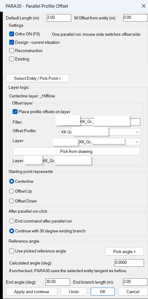
30Parallel
✅ Produces clean parallel utility profile geometry with centerline, left and right offsets, controlled layer naming, and optional 30 degree branch continuation.
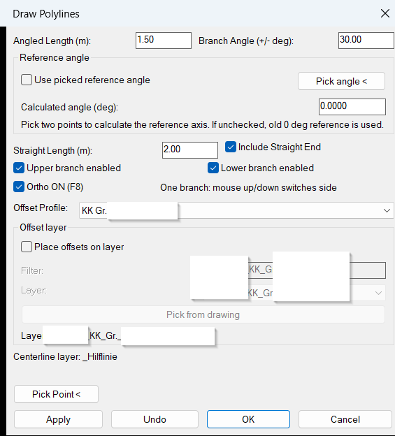
30Degree
Comming soon …ReplaceBlock
✅ The selected block references are replaced with the chosen block definition while keeping their main geometric placement and display properties.
✅ The workflow is faster than manually deleting, reinserting, scaling, rotating, and relayering blocks one by one.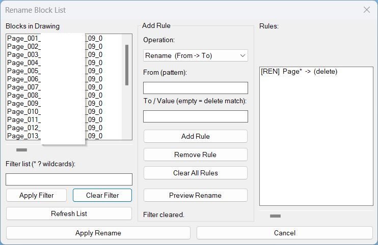
RenameBlockList
✅ The result is a cleaner and more standardized AutoCAD drawing with block definitions renamed in bulk according to user-defined rules. It is useful for CAD cleanup, block library normalization, imported DWG correction, BIM/CAD production standards, and discipline-specific block naming workflows.
CopyRenameBlockChangeLayer
✅ The result is an independent renamed block copy or renamed block reference with controlled layer assignment, cleaner ByLayer graphics, and preserved dynamic-block behavior.
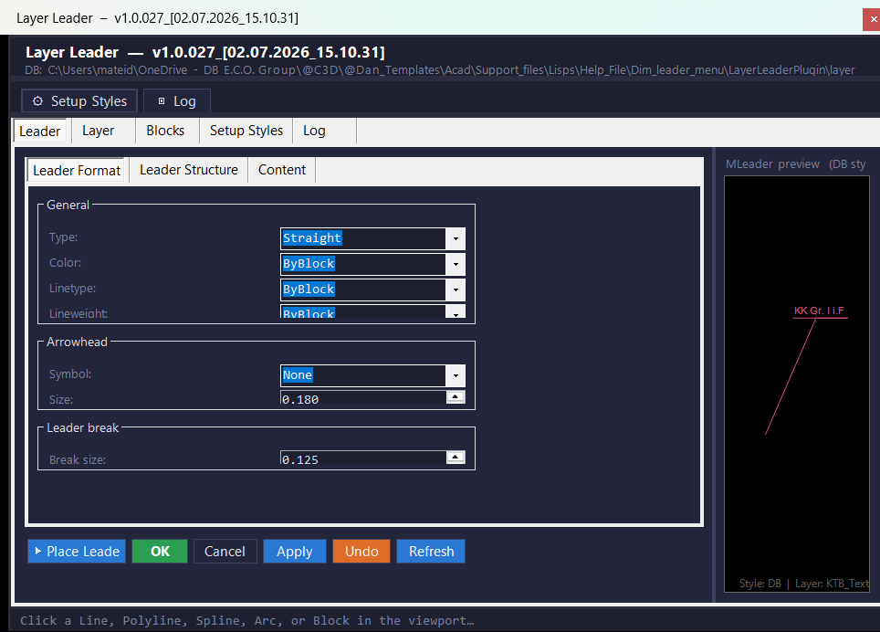
LayerLeaderPlugin
🎯 The result is a controlled annotation workflow for AutoCAD and Civil 3D: users can place consistent MLeader labels, manage layer and block label rules, update linked labels, clean style overrides, and keep project annotation standards synchronized from one modeless plugin panel.
📊 The tool is useful for CAD managers, Civil 3D production teams, infrastructure designers, and drafting users who need repeatable leader labels, structured layer naming, dynamic block annotation rules, and cleaner drawing standards.
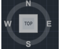
NavvCubeDisplayOffOn
✅ The result is a quick AutoCAD display utility that refreshes the Navigation Cube or NavVCube state from a single command, making it easier to restore visual navigation controls during drafting and Civil 3D production work.
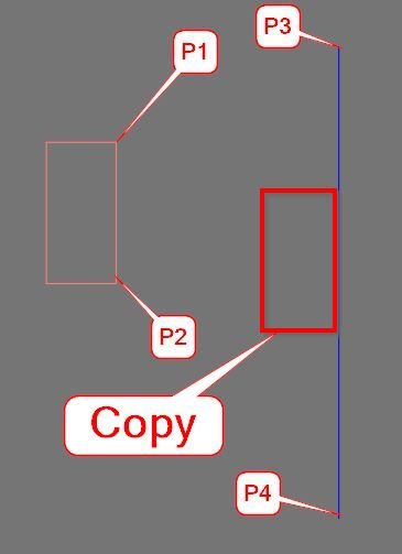
CopyMove2MidPoint_vs.01
✅ The result is a precise midpoint-alignment workflow for quickly moving or copying selected AutoCAD objects from one reference location to another.
🏗️ It is useful for CAD alignment, infrastructure drafting, block/object repositioning, profile or section drafting assistance, and repeated object placement where midpoint reference control is faster than standard manual MOVE or COPY workflows.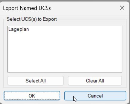
Export_Import_MS_UCS
🎯 The result is a faster AutoCAD UCS management workflow where named User Coordinate Systems can be exported, archived, shared, imported, and reused between drawings.
✅ CAD users can preserve project UCS standards, improve drawing setup consistency, and reduce manual UCS recreation during Civil 3D and AutoCAD production work.
XrefDrawingOrder
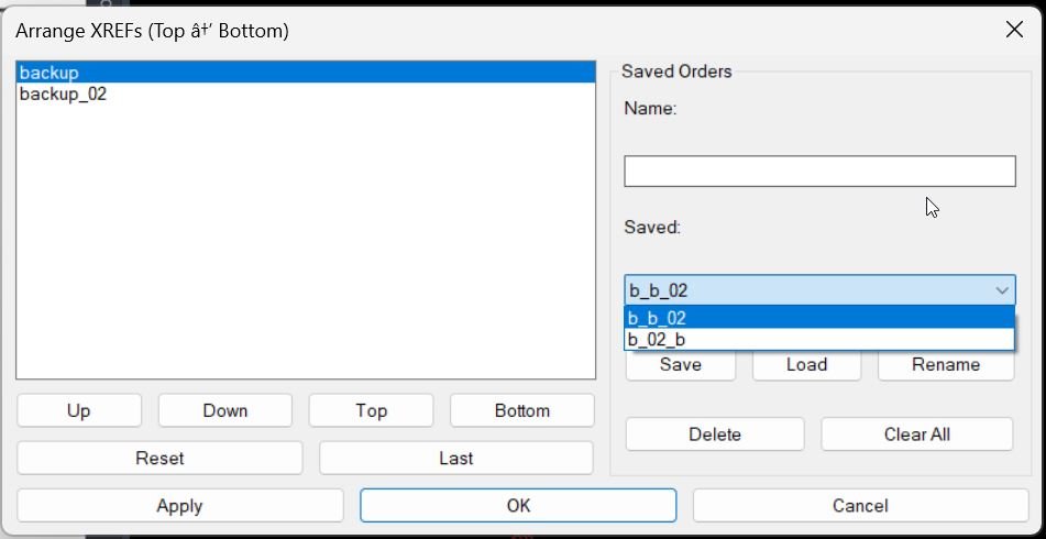
✅ The result is a faster AutoCAD xref draw order workflow for large reference-based drawings.
🧭 Users can control background surveys, layout sheets, design xrefs, utilities, corridors, alignments, basemaps, and annotation references with a reusable visual ordering workflow.
📐 The command reduces repetitive manual DRAWORDER operations and makes xref stacking more predictable in AutoCAD and Civil 3D production drawings.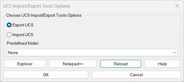
ExpImpUCS
🎯 The result is a faster and more controlled UCS management workflow for AutoCAD and Civil 3D.
📤 Users can export named UCS definitions from one drawing, share the .ucs file, and import the same coordinate systems into another drawing.
📥 The tool improves drawing setup consistency, reduces repetitive UCS recreation, and supports project-based folder structures used in infrastructure and Civil 3D production.
✅ ExpImpUCS is especially useful when multiple drawings must share the same custom UCS definitions for Lageplan work, xref coordination, layout checks, and repeated CAD standards.AreaCalc
✅ The result is a labeled and calculated area schedule for selected closed AutoCAD geometry, with converted values, totals, and optional linked field expressions.
📊 Depending on the selected report type, the user receives a placed drawing table, a text based schedule in model space, a TXT report, or a CSV report for Excel and quantity workflows.
LinetypeWithCharacters2
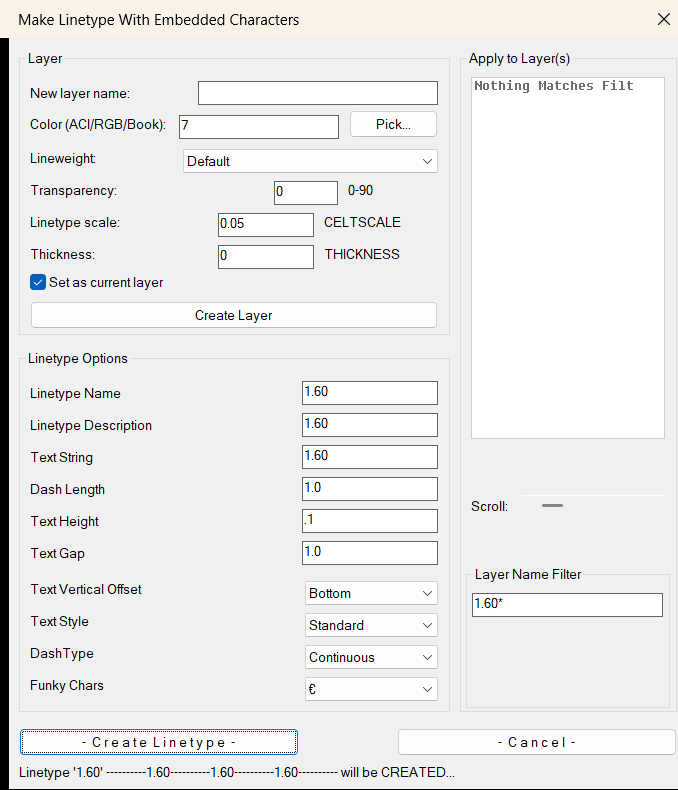
✅ The result is a custom AutoCAD linetype loaded into the drawing and assigned to the chosen layer or layers.
✅ The selected layer can also be created or updated with color, lineweight, transparency, CELTSCALE, THICKNESS, and current-layer settings.
✅ The workflow reduces manual LIN file editing and makes it faster to create production-ready text-based linetypes for CAD and Civil 3D drawings.
LinFileDraw_vs.01
✅ The result is a clean AutoCAD linetype sample legend generated from a LIN file, with selected linetypes drawn as scaled polyline examples and labeled with readable MText.
📌 This is useful for CAD managers, Civil 3D template maintainers, drafting teams, and users who need to validate custom linetypes, prepare linetype documentation, or compare LIN definitions directly in model space.
LinFileDraw
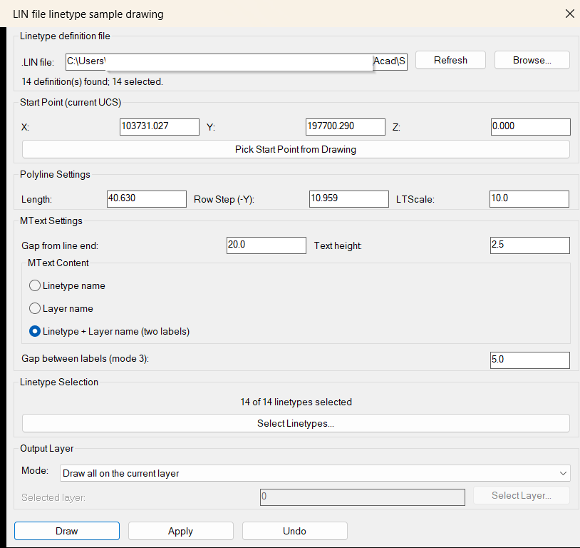
✅ The result is a clean AutoCAD linetype sample legend generated from a LIN file, with selected linetypes drawn as scaled polyline examples and labeled with readable MText.
📌 This is useful for CAD managers, Civil 3D template maintainers, drafting teams, and users who need to validate custom linetypes, prepare linetype documentation, or compare LIN definitions directly in model space.
XrefOffsetLayer
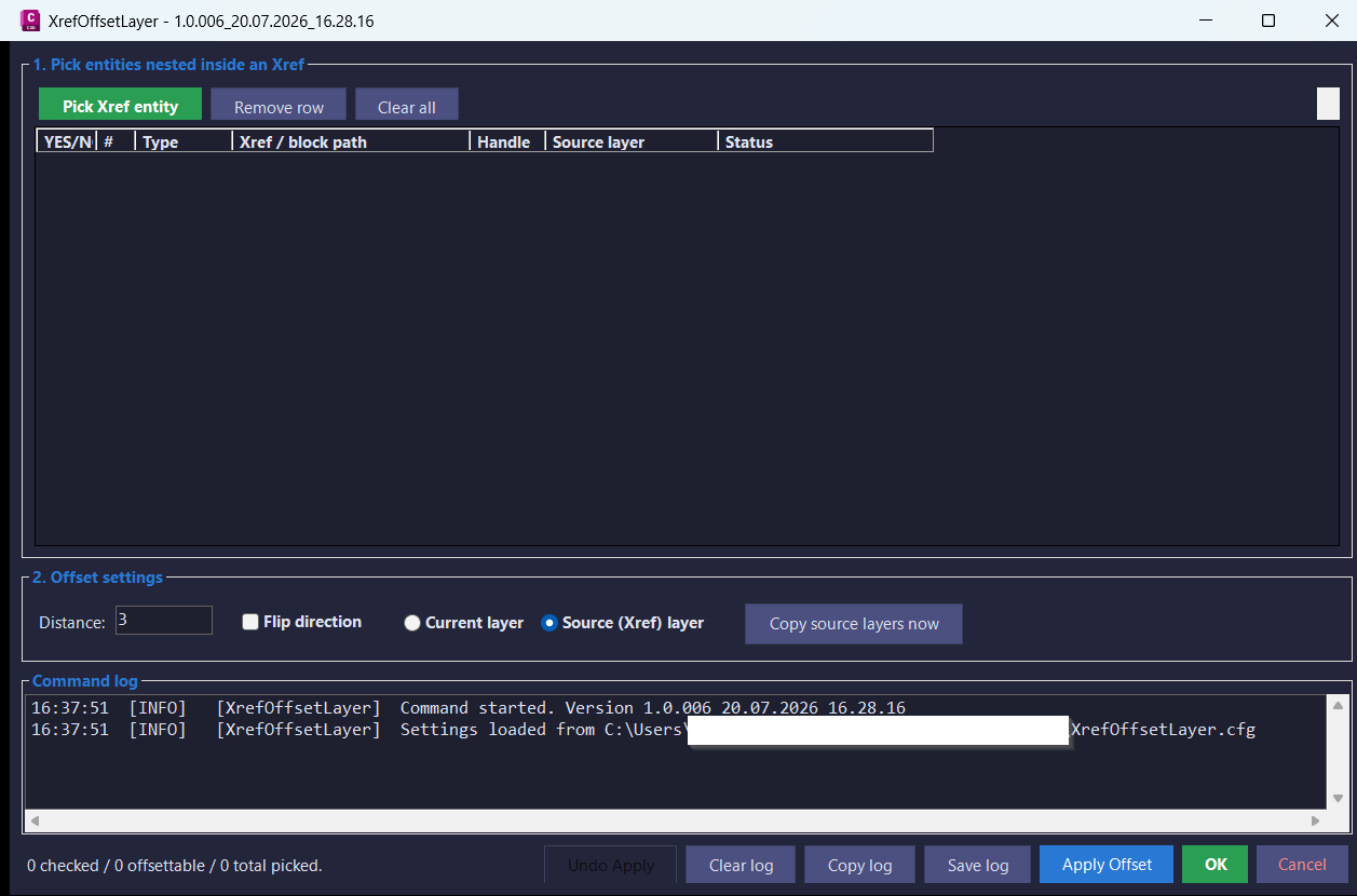
✅ The result is a safer and faster AutoCAD Xref offset workflow: selected Xref curve geometry is recreated as real host-drawing geometry, offset by the requested distance, with optional source-layer cloning and a visible audit trail.
This improves Civil 3D production efficiency when users need offset geometry from references without binding, exploding, or manually tracing Xref content.
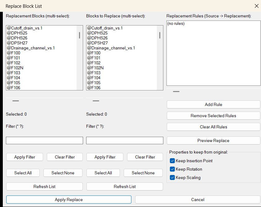
ReplaceBlockList
✅ The result is a faster and safer AutoCAD block replacement workflow for drawings with many repeated symbols, details, callouts, blocks, or CAD standard updates.
🔁 Instead of manually finding, copying, placing, rotating, scaling, and deleting block references one by one, ReplaceBlockList lets the user define multiple source-to-replacement rules and process them in a single batch.
📊 The preview dialog gives a clear count of affected source instances before replacement, helping reduce mistakes in large drawings.
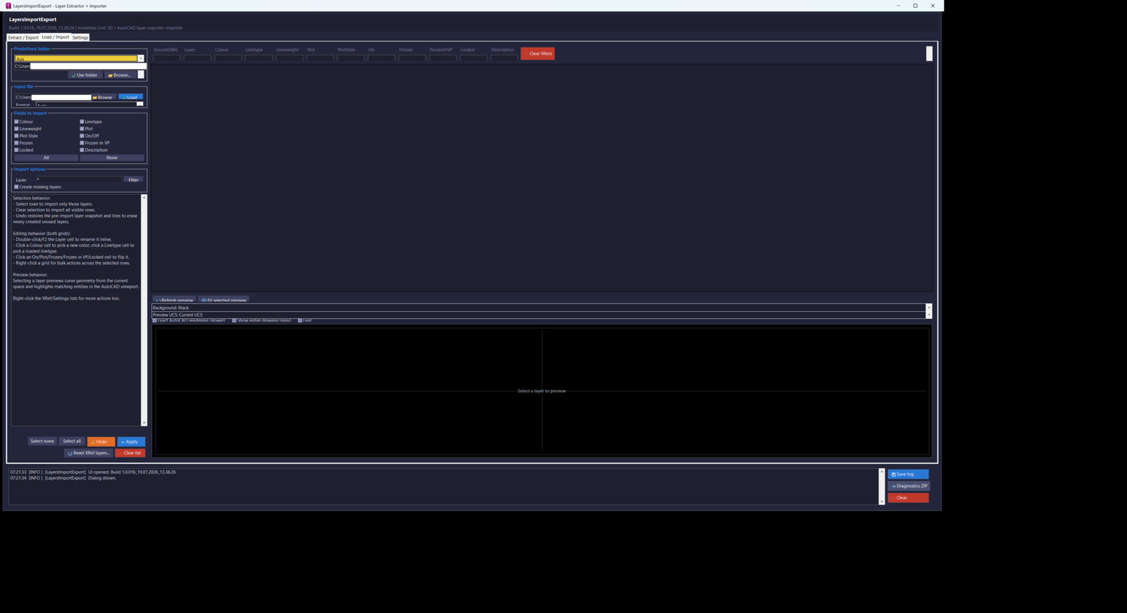
LayersImportExport
The project transfers complete or selected layer standards between AutoCAD drawings and CSV or XML files, applies edited or imported properties to the active drawing, resets Xref layer overrides from source files, previews layer geometry, and restores the latest layer-changing operation through Undo. It supports both one-drawing and multi-DWG workflows while providing filters, progress, cancellation, project-folder presets, logging, and diagnostics.
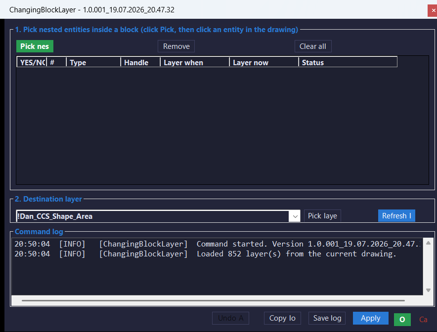
ChangeBlockLayer
The project changes the Layer property of checked, modifiable entities selected inside block references. Because the selected ObjectId belongs to the block definition rather than to an exploded copy, the modification is applied to the actual block content. The grid, individual highlighting, Xref detection, destination-layer validation, confirmation prompt, live logging, and session-level Undo Apply provide control over the operation.
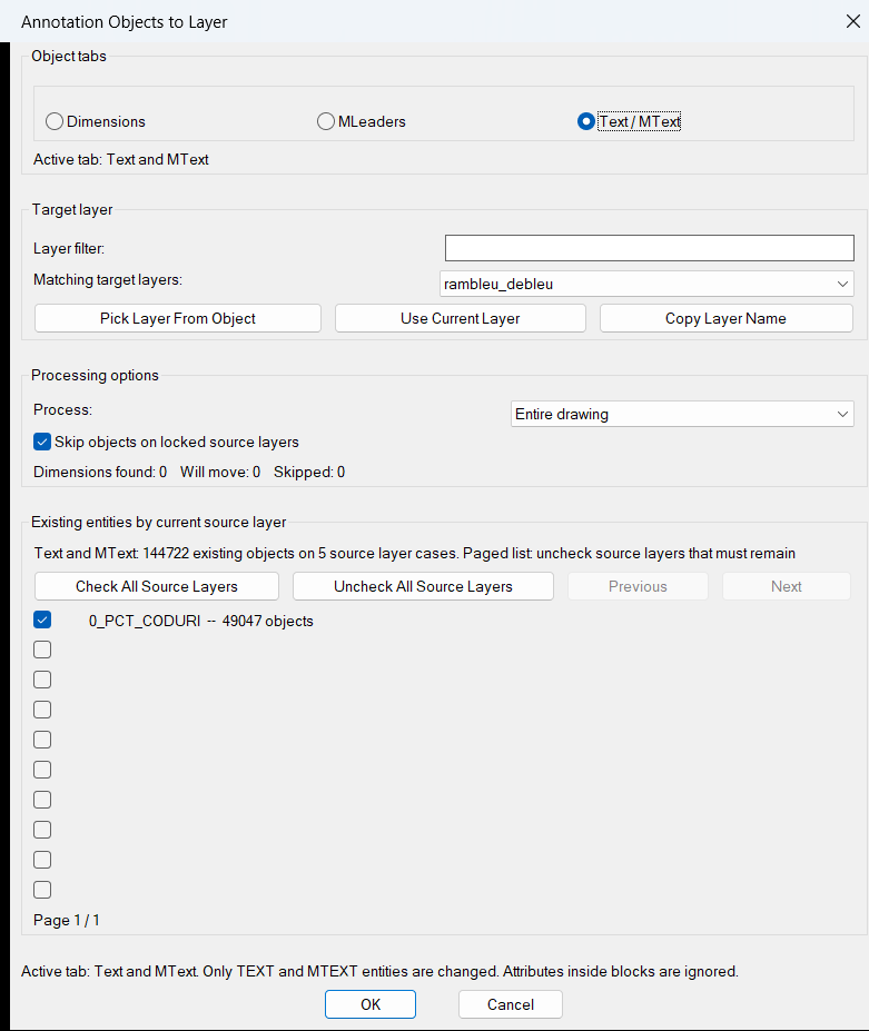
Entities2Layers
The routine moves enabled dimensions, multileaders, text, or mtext objects from their current source layers to the selected target layer. It applies the chosen drawing scope, source-layer selections, and locked-layer rules, reports processing totals, and preserves disabled source layers and inactive annotation categories unchanged. Optimized counting and guarded row processing improve responsiveness and reliability in drawings containing large annotation sets.
ExplodeLinetype
The routine replaces selected TEXT and MTEXT objects with editable exploded line geometry. When the primary ExplodeLinetype command is used, the resulting entities are standardized on layer MISC with Continuous linetype, ByLayer color, and ByLayer lineweight.
AutoTrimExtendLines
🎯 Result:
AutoTrimExtendLines provides a faster CAD cleanup workflow for extending and trimming selected geometry to bounding edges. The user can pick boundary objects, pick objects to modify, apply the operation, review the debug result, undo if needed, and continue working from the same dialog.
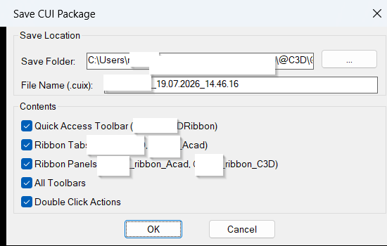
SaveCUIX
The command produces a new filtered .cuix file at the selected output location. The exported package can contain only the required [username] ribbon tabs, [username] ribbon panels, [username] Quick Access Toolbar, toolbars, and double-click actions selected in the dialog.
ToolPaletteExporter
The result is a portable Tool Palette export package containing the selected XTP palette, related source files, optional palette image resources, and a clear missing-file report. The workflow helps CAD managers and AutoCAD users back up, transfer, audit, and document tool palettes without manually chasing every referenced LISP, DWG, icon, script, or support file.
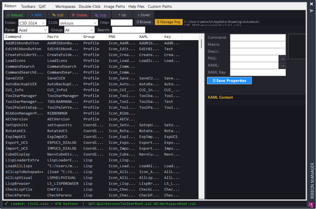
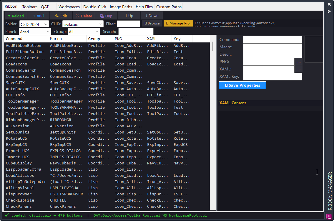
RibbonManagerPlugin
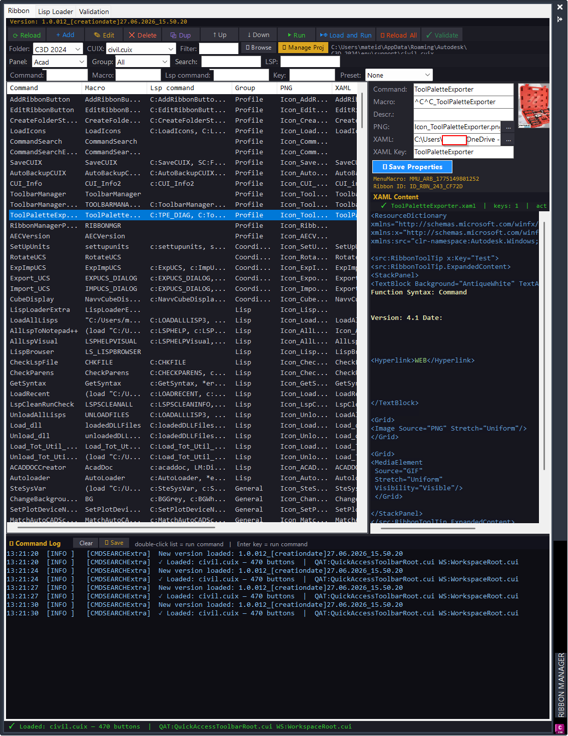
The result is a production-oriented AutoCAD and Civil 3D ribbon management plugin that reduces manual CUI editing work, makes ribbon command metadata easier to maintain, improves icon and help-file consistency, and allows fast updates to custom ribbon panels from a single modeless interface.
LoadIcons
The result is a faster AutoCAD and Civil 3D ribbon icon refresh workflow. Instead of manually copying PNG files and reloading CUI files, the user can run
LoadIconsto deploy icon updates to the support path and reloadCIVIL.cuixin one operation.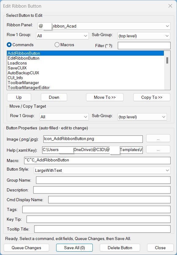
EditRibbonButton
The result is a faster and more controlled AutoCAD ribbon customization workflow. Users can update ribbon buttons, images, help tooltips, macros, command metadata, and command placement without manually editing CUIX XML or repeatedly opening the full CUI editor.
CreateFolderStructure
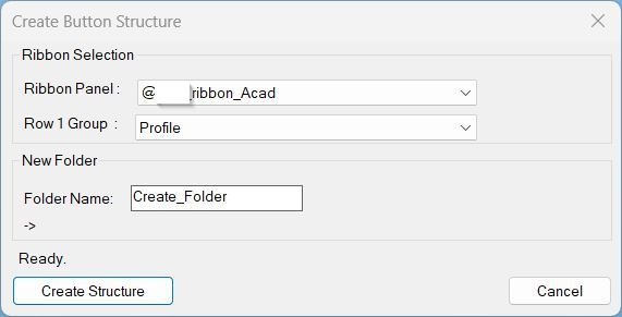
The result is a ready-to-use AutoCAD Help_File command folder for a new ribbon button. The generated folder includes the expected icon placeholder, LISP placeholder, XAML tooltip file, screenshot folders, and compiled support folders, placed in the correct ribbon and group-based Help_File location.
CommandSearchExtra
The result is a centralized AutoCAD and Civil 3D command administration environment. CAD managers can audit Ribbon commands, validate CUIX links, detect missing LISP files, load support tools, repair metadata, export reports, and produce command documentation without manually searching through CUIX XML, support folders, or scattered toolbar resources.
CommandSearch Lisp Loader Only
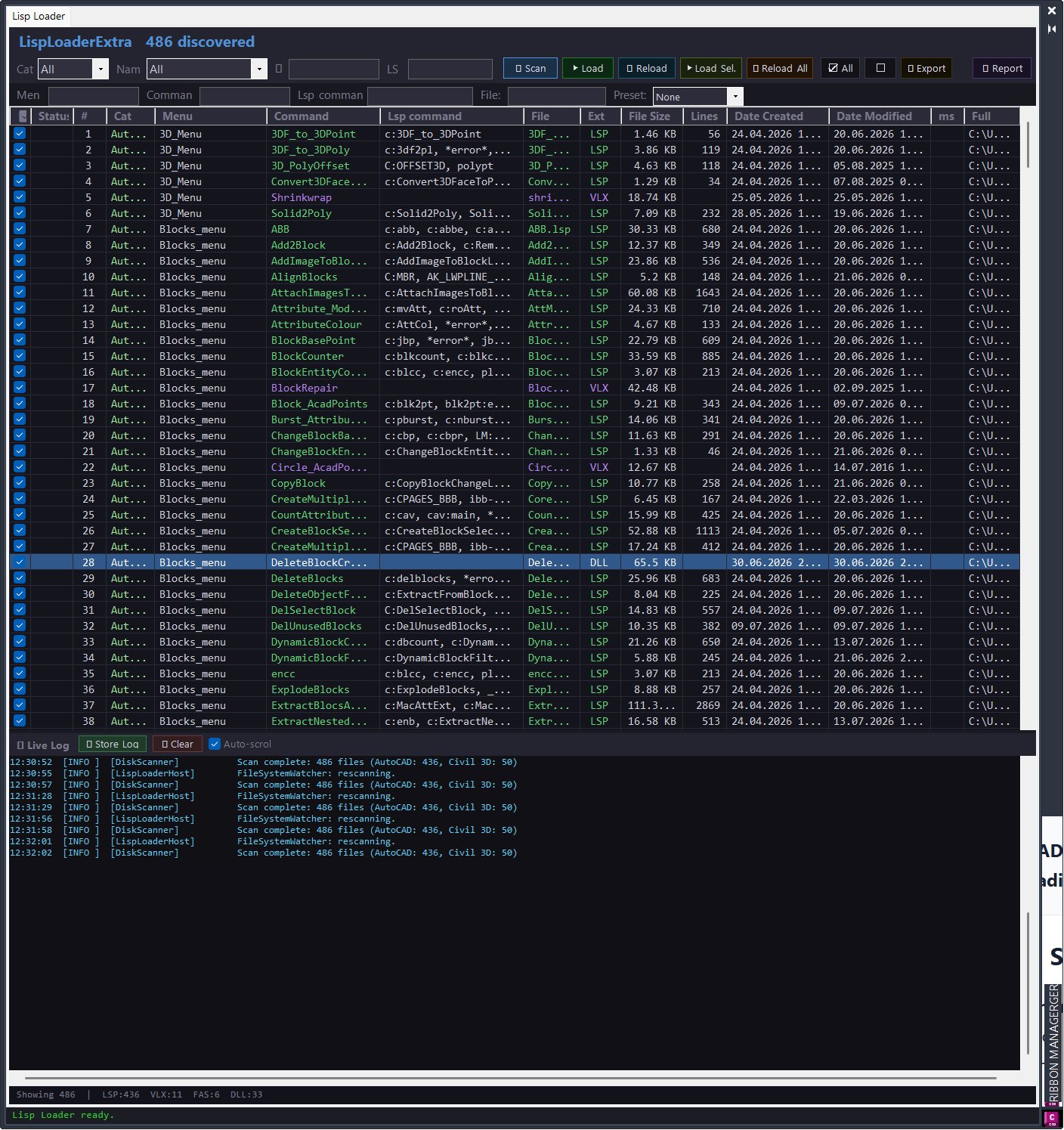
The result is a centralized CAD command administration tool that helps teams keep AutoCAD and Civil 3D ribbon buttons, LISP loaders, CUIX metadata, help references, images, and command libraries organized and easier to validate.
It is especially useful when a production environment contains many custom commands, many Help_File folders, many partial CUI entries, and frequent LISP or DLL updates that need to be scanned, loaded, reported, and verified.
AutoBackupCUIX
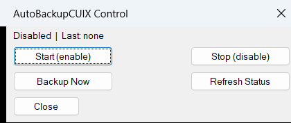
The result is a timestamped, filtered backup copy of CIVIL.cuix saved to the configured menu folder. When enabled, the routine protects the Civil 3D customization environment once per day and gives the user manual control through command-line commands or the AutoBackupCUIX dialog.
AddRibbonButton
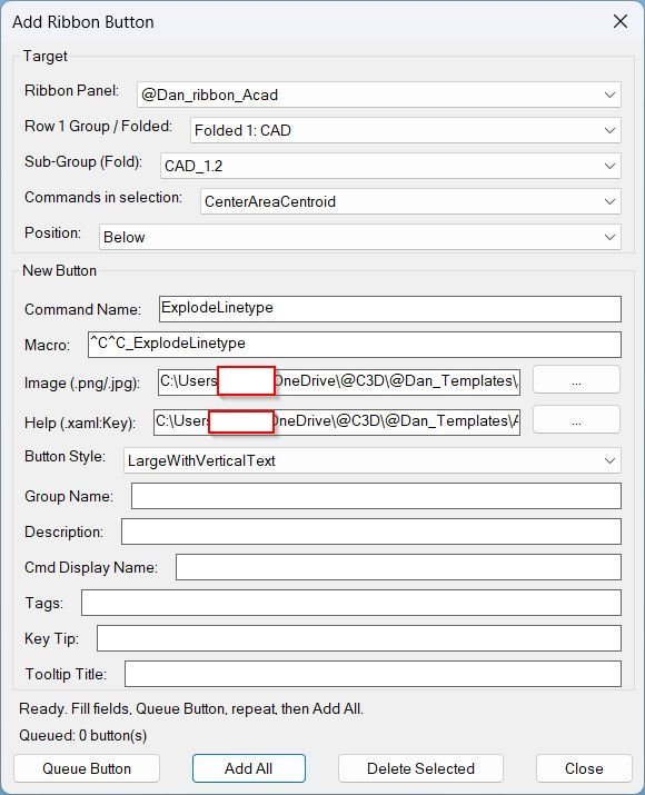
The result is a faster and more controlled AutoCAD ribbon button creation workflow for CAD support folders, CUIX maintenance, help system linking, custom image assignment, and production ribbon organization.
AECVersionPlugin
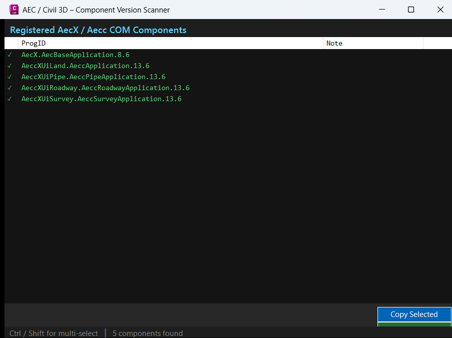
The result is a clean Visual Studio project file for compiling AECVersionPlugin.dll, an AutoCAD and Civil 3D diagnostic plugin intended to run through the
AECVERSIONcommand afterNETLOAD.It provides the build foundation for a managed AEC version scanner while preserving the correct Autodesk reference behavior required by AutoCAD plugin deployment.
ToolbarManager_vs.01
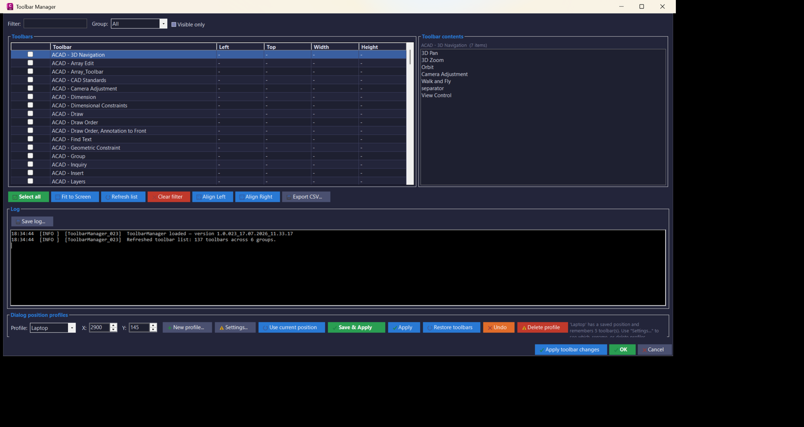
✅ The final result is a productivity-focused AutoCAD Civil 3D toolbar layout manager that centralizes toolbar discovery, visibility control, monitor-aware positioning, profile storage, profile restore, toolbar-set editing, CSV export, clipboard workflows, and diagnostic logging.
🟢 It reduces manual AutoCAD UI setup, improves multi-monitor Civil 3D workflow recovery, makes toolbar layouts repeatable across workstations, and helps CAD teams standardize floating toolbar arrangements with fewer repetitive steps.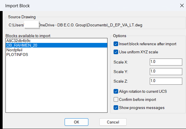
ImportBlock
✅ The final result is a focused AutoCAD and Civil 3D block import workflow that lets users pull clean block definitions from external drawings, optionally insert them with controlled scale and UCS rotation, and keep common import settings saved for repeat use.
It improves block library reuse, drawing setup speed, CAD standardization, production drafting efficiency, and DWG management while reducing repetitive manual block import steps.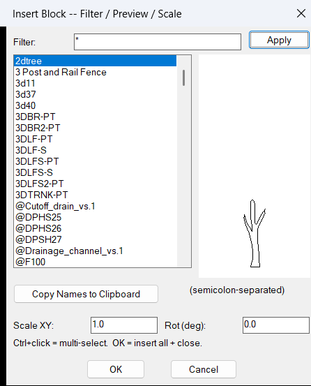
InsertBlockFilterScale
✅ The final result is a faster AutoCAD and Civil 3D block insertion workflow where users can search existing blocks, preview geometry, insert multiple symbols, apply scale and rotation, and reuse saved settings.
It reduces repetitive block browsing, improves CAD drafting productivity, supports standard block library usage, and makes DWG block insertion more controlled and efficient.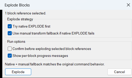
ExplodeBlocks
✅ The final result is a practical AutoCAD and Civil 3D block cleanup tool that helps users explode protected, difficult, or non-uniformly scaled block references into editable geometry.
It reduces manual block troubleshooting, improves DWG editing productivity, supports drawing cleanup, and helps CAD users prepare block-based drawings for editing, coordination, export, and quality control.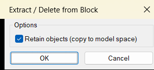
DeleteObjectFromBlock
✅ The final result is a practical AutoCAD block editing and cleanup tool that lets users extract useful nested geometry from block definitions or delete unwanted internal objects with fewer manual steps. It improves DWG cleanup, block maintenance, CAD production speed, and drawing quality control by combining a simple DCL interface with direct nested entity selection and automated block definition editing.
DeleteBlockCrossings
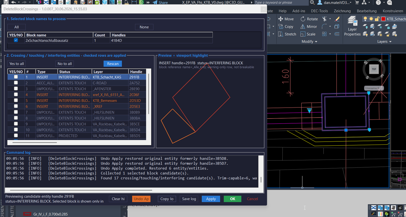
✅ The final result is a practical AutoCAD and Civil 3D cleanup plugin that helps users identify and remove unwanted curve segments passing through selected blocks. It reduces manual trimming, improves DWG quality control, documents crossing diagnostics, supports visual review, and keeps a reversible apply workflow for safer production drawing cleanup.
CreateMultipleRectangleBlocks
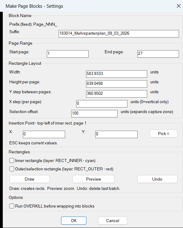
✅ The final result is a faster AutoCAD and Civil 3D workflow for creating repeated page rectangles, collecting drawing geometry by page zone, and generating organized block references with consistent names. The tool reduces manual window selection, speeds up block creation, improves DWG structure, and supports more reliable drawing cleanup and production sheet management.
CopyBlock_vs.01
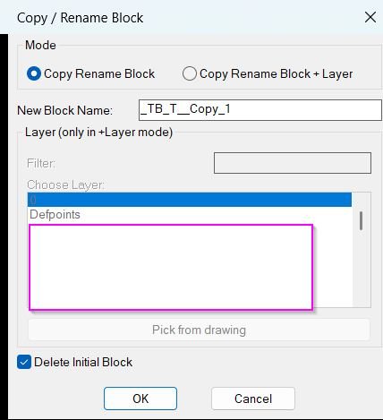
✅ The final result is a faster AutoCAD block management workflow: the user selects one block reference, creates a new independent block definition, optionally applies a CAD layer standard, optionally forces new block contents to ByLayer, and can remove the original block reference in the same operation.
This improves DWG organization, reduces manual block rename work, supports cleaner layer control, and helps CAD teams create reusable block variants with fewer repetitive AutoCAD steps.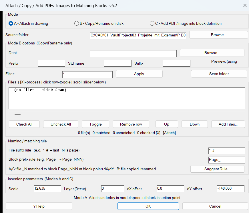
AttachImagesToBlocks
✅ The final result is a practical AutoCAD and Civil 3D automation tool that connects external PDF and raster image files with named drawing blocks, attaches them at the correct insertion points, copies and renames files for document management, or embeds underlays directly into block definitions. It reduces repetitive manual attaching, improves sheet-to-block coordination, speeds up DWG preparation, and supports cleaner CAD and Civil 3D production workflows.
Convert3DFaceToPolyline
✅ The final result is an AutoCAD and Civil 3D workflow description for converting selected
3D Faceobjects into closedPolylineboundaries. It reduces manual tracing, improves drawing cleanup, makes face-based geometry easier to edit, and gives CAD users a clearer production workflow for managing 3D face outlines in DWG files.3DF_to_3DPoly
✅ The final result is a practical AutoCAD and Civil 3D AutoLISP utility that converts selected 3DFACE objects into closed 3D polylines with elevation-aware vertices. It improves drawing cleanup, makes legacy 3D face geometry easier to edit, reduces manual tracing, and supports faster 3D CAD and Civil 3D production workflows.
BookmarkEntities
✅ The final result is a focused AutoCAD AutoLISP bookmark manager that helps users record important entity locations, organize them by object type, add remarks, and zoom back to saved drawing areas quickly.
It reduces repetitive manual navigation, improves drawing review workflows, supports better CAD quality control, helps users manage object-based notes, and makes large AutoCAD and Civil 3D drawings easier to inspect.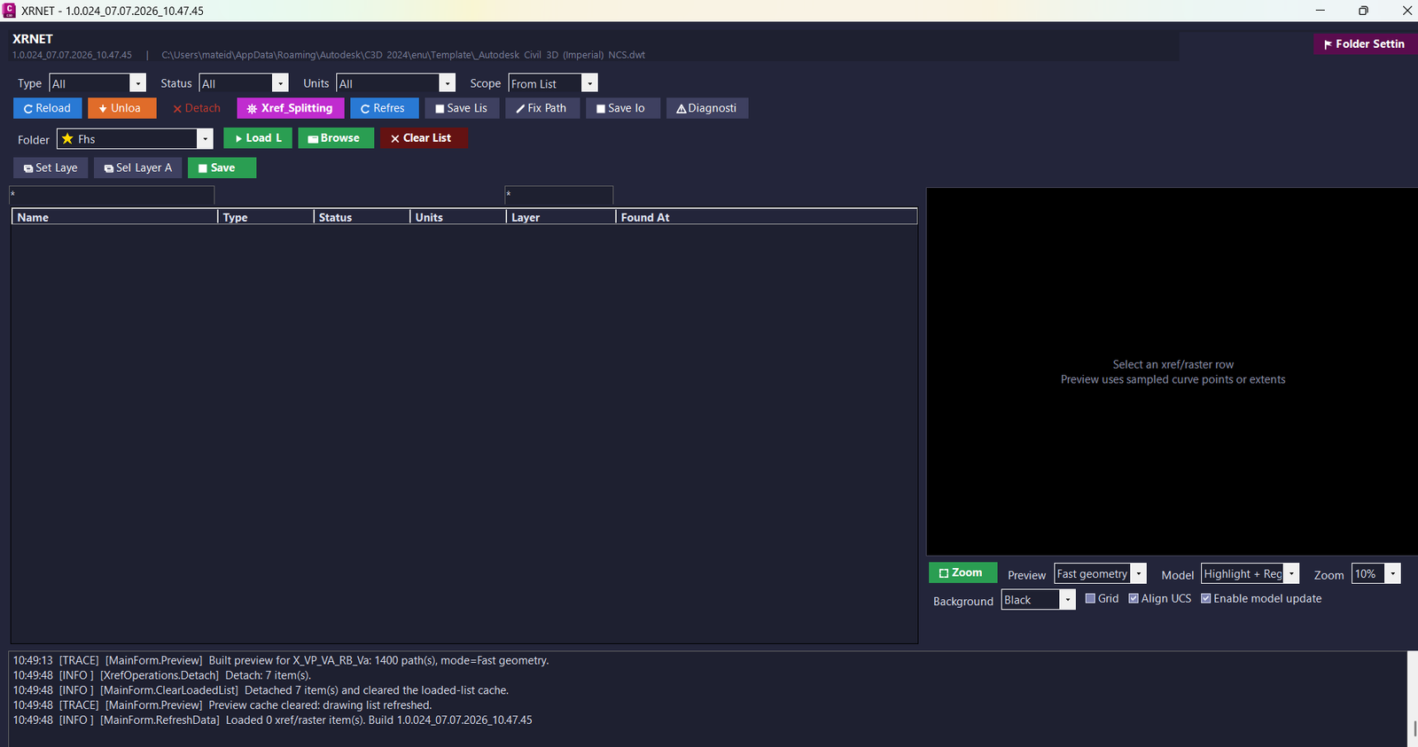
XrNet
✅ The final result is a productivity-focused AutoCAD and Civil 3D xref management plugin that centralizes DWG xrefs, raster images, paths, status, preview, export, diagnostics, and cleanup actions.
It reduces repetitive manual work, improves external reference quality control, detects missing paths, speeds up project setup, improves drawing organization, and supports cleaner Civil 3D and AutoCAD production drawings.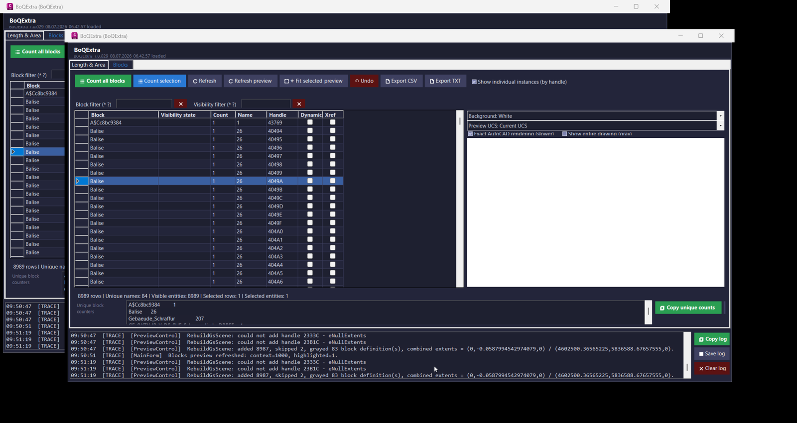
BoQExtra
✅ The final result is a productivity-focused AutoCAD and Civil 3D quantity takeoff plugin that combines geometry measurement, dynamic block counting, formula generation, field-based MTEXT placement, preview validation, entity editing, model-space synchronization, and export automation in one interface.
🚀 BoQExtra reduces repetitive manual measurement, prevents copy-paste mistakes, improves BoQ traceability, speeds up block and layer checking, and helps users create cleaner construction quantity documentation with fewer manual steps.
🔐 Important configuration note: the project targets
.NET Framework 4.8and requires AutoCAD or Civil 3D managed API references throughAutoCAD_Civil3D_references.propsor a user-specific ObjectARX reference path. Profiles and logs are stored in%APPDATA%\BoQExtra.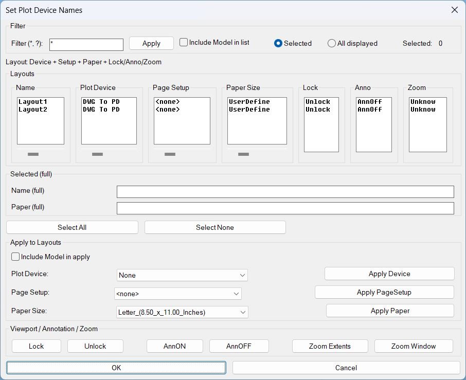
SetPlotDeviceNames
🎯 Layout plotting settings can be cleaned and standardized faster across many sheets.
🖨️ Plot device, page setup, and paper-size mismatches become easier to find and correct.
🔒 Viewport lock, annotation, and zoom preparation are handled in the same production dialog.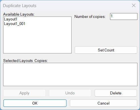
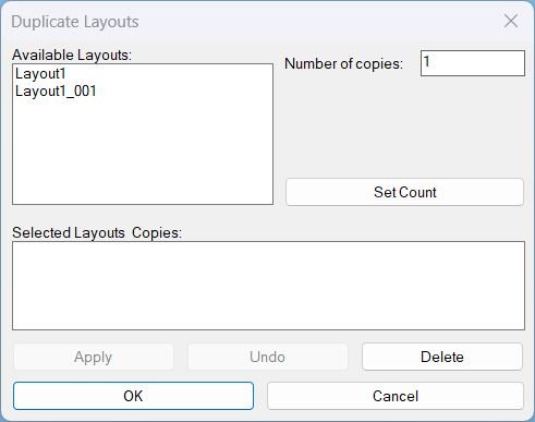
DuplicateLayouts
🎯 The result is a faster layout duplication workflow for AutoCAD and Civil 3D drawings.
📄 Users can create many paper-space tabs from existing layouts without repeating manual LAYOUT Copy operations.
✅ DuplicateLayouts improves sheet setup speed, reduces layout naming mistakes, and supports consistent production drawing preparation for plotting, plan sheets, and sheet-set workflows.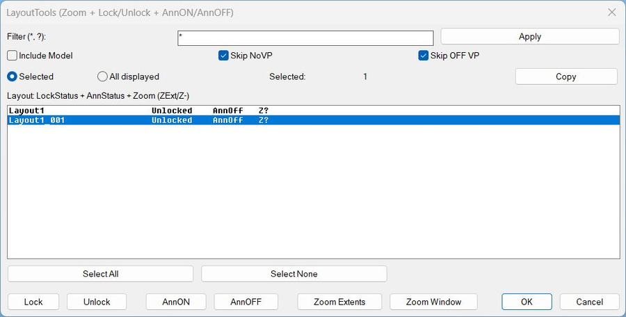
LayoutTools
🎯 The result is a centralized layout QA and viewport management workflow for AutoCAD and Civil 3D drawings.
🔒 Users can protect viewport scales, control annotation visibility, and synchronize zoom views across many sheets from one dialog.
✅ LayoutTools improves plan set cleanup, plotting consistency, sheet navigation, and production drawing review.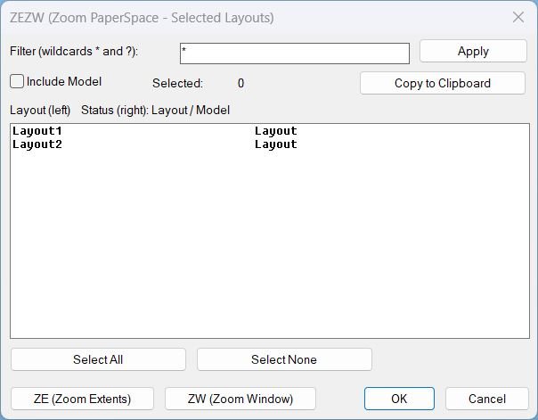
Zoom Extend Window
Result summary The routine provides a stable dialog-driven way to select layouts, optionally include Model, copy selections to clipboard, then apply zoom extents or a consistent zoom window in Paper Space across the selected layouts. Tags Layouts, Paper Space, DCL, Dialog_UI, Clipboard, Viewports, General_AutoCAD, Lisp, Extra_AutoCAD Suggest relevant tags not in the list Zoom, Wildcards, Undo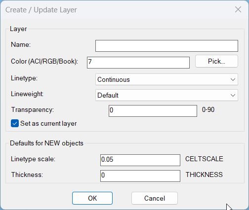
LayerCreation
🎯 The result is a correctly created or updated AutoCAD layer with the desired CAD-standard properties.
🟢 The user gets a direct message confirming the layer name that was created or updated.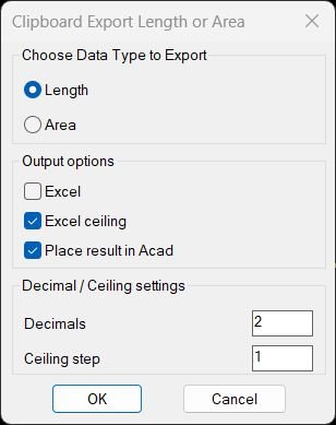
TotalLengthAreaDetailed
✅ The result is a faster AutoCAD and Civil 3D quantity takeoff workflow: selected entities are measured, a clean expression is built, the value is copied for Excel, and an optional drawing annotation is inserted as MTEXT. Where possible, the MTEXT uses AutoCAD field expressions linked to the selected objects, while unsupported objects fall back to fixed numeric values.
CopySelection_vs.01
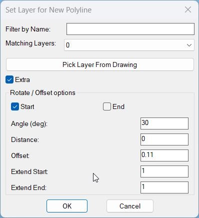
Result: A new polyline segment is created from the selected portion of the original LWPOLYLINE, placed on the chosen layer, and optionally extended, rotated, shifted, and replicated as multiple offset copies according to your dialog settings. • Efficient profile building: Complex pipe or band arrangements along an alignment can be generated from a single base polyline, with each functional run duplicated and positioned with precise numeric control rather than manual edits. • Consistent offsets and angles: Repeated elements share the same extension, rotation, distance, and offset parameters, giving your layout a uniform and standards compliant appearance. • Safe experimentation: Apply and Undo inside the dialog let you experiment with different combinations of offsets, angles, and extension distances, knowing that Cancel can revert everything and OK will keep the final configuration in a single undo block. • Workflow memory: The command remembers your last layer and filter, so subsequent runs in the same project feel streamlined with minimal repetitive input. Copy code:3DPolyVertex2Table
🎯 The result is a coordinated table and drawing markup set that directly relates every 3D polyline vertex to its X Y Z values.
📋 This is useful for survey geometry design review setting out and coordinate documentation.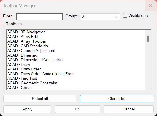
ToolbarManager
Result: Your AutoCAD toolbars are updated so that only the toolbars selected in the current filtered view are visible, while all other toolbars in that view are hidden, giving you a clean, customized toolbar layout. • Faster workspace management: You can switch between different toolbar sets in seconds, without editing the CUI or manually toggling individual toolbars on and off. • Reduced clutter: Unused toolbars are easily hidden based on simple filters and group selections, improving available screen space and focus on your current task. • Repeatable setups: Because the manager remembers your last view, it is easy to revisit and refine the same toolbar configuration throughout a project session. • Clear feedback: The list preselection shows which toolbars are visible before and after applying, and a short message confirms when toolbars have been updated. Copy code: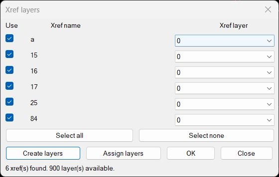
CreatesXrefsLayersAssign_vs.00
Result / Outcome: All selected xrefs are moved to the layers chosen in the dialog, so each external reference can live on its own dedicated layer (for example _xref_xrefname) for better control of visibility, plotting, and color. This makes it very fast to standardize xref layers across drawings without manually searching for each xref insert.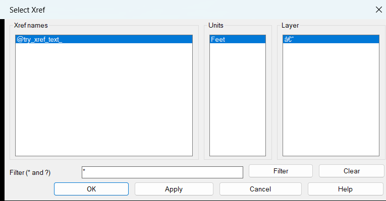
ZoomXref
The result is a faster AutoCAD Xref navigation workflow. Users can find an external reference by name, confirm its units and layer context, then zoom immediately to the selected Xref extents without manually hunting through the drawing.
XRefs2Layers
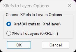
✅ The result is a cleaner AutoCAD drawing where XREF references are organized on predictable layers.
📂 CAD teams can quickly isolate, freeze, lock, audit, or plot XREF content by using either one shared _XREF layer or separate 0-XREF_ layers.
📊 The final alert gives immediate feedback about how many XREF references were moved to each layer.
XrefsDrawingOrder
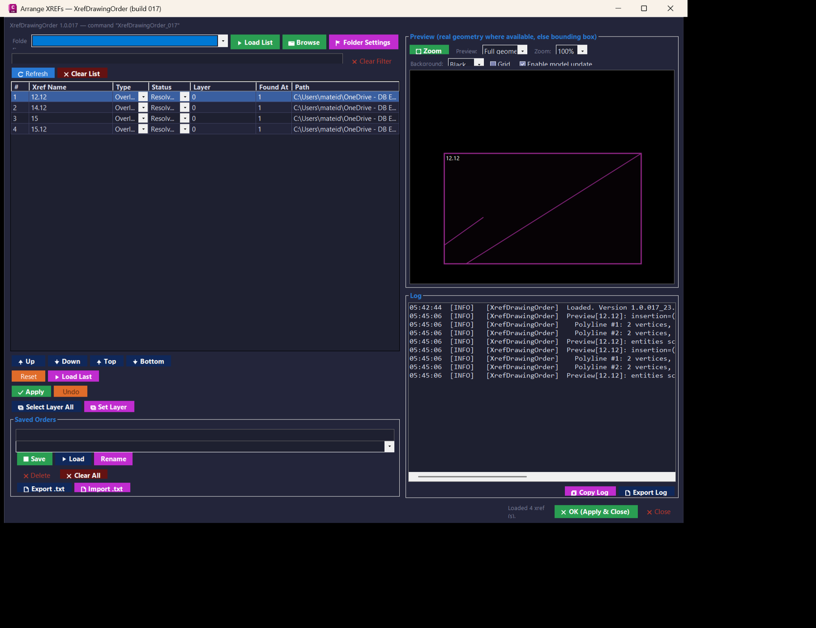
✅ The result is a controlled, repeatable AutoCAD xref draw order workflow. Users can inspect every external reference, reorder the visual stacking, save standard xref arrangements, preview the result, apply the order, and undo the last applied change without relying on repeated manual DRAWORDER picks.
🚦 In production drawings, this helps keep base maps, corridors, utilities, surveys, construction plans, labels, and discipline-specific xrefs visually organized and easier to audit.
Multiple_text_mtext_2
Result: All selected TEXT and MTEXT objects are replaced by a single MTEXT entity that preserves line order, paragraph separation, and underline formatting while matching the original visual style. • Cleaner editing: You can now edit the combined content in one MTEXT editor instead of handling many separate text entities. • Consistent appearance: The new MTEXT inherits layer, color, style, height, alignment, and rotation from the first selected text item. • Preserved structure: Individual lines from plain TEXT are kept as separate paragraphs, and underline codes are correctly converted to MTEXT format. • Non reversible by command: Original text entities are deleted once the MTEXT is created, so the change is final unless you use Undo. Copy code:Copy_to_Clipboard_Xref
Result: All text gathered from your picked nested entities is extracted, combined, and copied directly into the Windows clipboard. • Accurate extraction: TEXT + MTEXT + DIMENSION override/measurement + LEADER annotation + BLOCK attributes. • Fully automatic cleanup: All temporary entity copies used to extract text are deleted automatically. • Clipboard-ready output: Final text is immediately paste-ready for Excel, Word, Notepad, emails, or documentation. • Unmodified drawing: No permanent entities remain from the extraction process. Copy code: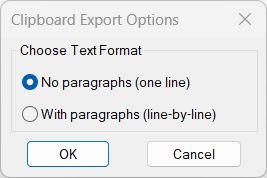
Copy_to_Clipboard
Result: The selected annotation content is cleaned, normalized, stripped of formatting codes, and copied directly to the Windows clipboard in the chosen text format. • Mode 1 (rb01): Produces one continuous clean text line suitable for Excel cells, filenames, or compact notes. • Mode 2 (rb02): Produces structured multi-line text for documentation, emails, or reports. • Clean Output: All MTEXT formatting, Unicode escapes, control codes, and garbage strings are removed, leaving readable plain text only. • Universal Use: The clipboard result can be pasted instantly into Word, Excel, Notepad, Outlook, or any external application. Copy code:RotateMtextVport
Result:- All selected MTEXT objects become horizontally oriented (0° rotation)
- All selected TEXT objects rotate to match the viewport orientation
- Text readability is improved in rotated viewports
Lower
Result: All selected TEXT and MTEXT entities are converted to the chosen case (Upper or Lower) instantly. • Uniform Formatting: Every selected annotation ends with consistent capitalization across the drawing. • Non-destructive: Only the text content changes — layer, style, color, rotation, and position remain untouched. • Clean Execution: System settings are restored automatically, leaving the environment unchanged after the command finishes. • Immediate Feedback: The text updates visually in the drawing as soon as the command loops through all entities. Copy code:Upper
All selected TEXT and MTEXT objects are converted to uppercase instantly.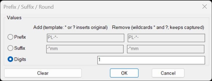
PrefixSuffixRound
• Transformed text entities — Selected TEXT, MTEXT, ATTRIB, and first attributes of INSERTs have their string content updated based on the chosen prefix, suffix, or rounding rules • Cleaned prefixes/suffixes — Unwanted leading or trailing patterns can be removed, even when partially matched with wildcards, while keeping important captured segments • Formatted numeric text — Number-only labels can be normalized to a consistent decimal precision using the Digits mode • Batch processing summary — After selection, the routine reports how many items were processed, giving quick feedback on scope • Reusable configuration — Users can repeat transformations on new selections without reconfiguring, thanks to stored PSOT_* environment values and helper commands PREF, SUFF, and OKR_TXTPlusMinusNumericValue
• Updated text content — All selected TEXT, MTEXT, ATTRIB, and ATTDEF objects have their targeted numeric portions incremented or decremented by the specified amount • Preserved formatting — Non-numeric characters, prefixes, suffixes, and MTEXT control codes remain unchanged, so labels and expressions keep their layout • Consistent precision — Decimal numbers are adjusted with respect to their existing precision (and the increment) with trailing zeros padded when required • Batch-friendly — Multiple selected entities are processed in one run with a single UNDO group, allowing quick sweeping renumbering or value adjustments • User convenience — Last used settings are remembered, making repeated plus/minus operations fast with minimal extra inputRegion2Polyline
• Polyline output Each REGION is converted into a clean closed LWPOLYLINE that accurately follows the REGION perimeter • Curvature preservation All arcs inside the REGION become proper polyline bulges, maintaining geometric fidelity • Consistent segment order The exploded segments are automatically sorted to produce a continuous, gap-free outline • Cleanup Original REGION objects and intermediate exploded entities are deleted to avoid clutter • Final geometry The resulting LWPOLYLINE is closed, planar, properly oriented, and ready for further use such as hatching, offsetting, area calculations, or contoursCopySelection
• Segment duplication A new LWPolyline reproducing only the selected portion of the original is created • Layer assignment The new polyline is placed on the chosen layer without altering the original object • Workflow benefit Enables quick extraction of partial runs for detailing, highlights, or separate layer control • Session persistence Stores last used filter and layer to speed up future usageCopySelection_vs.03
🎯 The result is one or more newly created lightweight polyline segments derived from the selected source curve portions.
📐 Depending on the selected options the result can also include rotated shifted extended repeated offset closed parallel and centerline geometry.
🧰 The tool is suitable for repeatable corridor utility cable protection and parallel geometry construction workflows.All_inside
🎯 The result is one active selection set containing the chosen boundaries and objects found inside them.
📦 The user can optionally preserve the complete selection as an AutoCAD group.LoadRecent
🎯 LoadRecent provides the described AutoCAD or Civil 3D workflow.
📌 The generated SEO description is based on the supplied source code or project files.loadedDLLFiles
🎯 @loadedDLLFiles provides the described AutoCAD or Civil 3D workflow.
📌 The generated SEO description is based on the supplied source code or project files.CheckParens
🎯 CheckParens provides the described AutoCAD or Civil 3D workflow.
📌 The generated SEO description is based on the supplied source code or project files.CheckLspFile
🎯 CheckLspFile provides the described AutoCAD or Civil 3D workflow.
📌 The generated SEO description is based on the supplied source code or project files.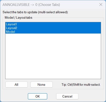
AnnoAllOff
🎯 The result is a controlled annotation visibility cleanup workflow for AutoCAD and Civil 3D drawings.
🔇 Users can turn off ANNOALLVISIBLE on all tabs or only selected layouts without manually switching each tab and typing the system variable.
📐 This supports plotting preparation, layout QA, annotative object cleanup, and drawing-standard workflows where visible annotation scales must be controlled per tab.SelectLayout
🎯 The result is faster layout navigation in AutoCAD and Civil 3D drawings.
📑 Users can jump to a required layout tab directly, which is especially helpful in drawings with many sheets or long tab names.
✅ SelectLayout improves CAD productivity by reducing manual tab searching.GoToLayout
🎯 The result is faster navigation through drawings with many layout tabs.
📑 Users can search for layout names, preview tabs, and jump directly to the needed sheet without manually scrolling along the layout tab bar.
✅ GoToLayout improves production navigation, sheet review, plotting preparation, and quality-control workflows in AutoCAD and Civil 3D drawings.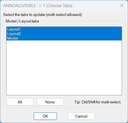
AnnoAllOn
- If the user confirms a selection, ANNOALLVISIBLE is set to 1 on each selected tab and the previous tab and mode settings are restored.
- If no tabs are selected, prints AAON: Nothing selected. No changes made.
- If the dialog is cancelled, prints AAON: Cancelled.
- If the dialog cannot be loaded, prints AAON: Could not load dialog.
- Always unloads the dialog and deletes the temporary DCL file at the end of execution.
Copy2Layouts
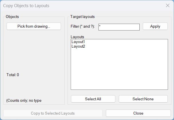
🎯 The result is a faster Paper Space object replication workflow inside a single AutoCAD or Civil 3D drawing.
✅ Users can place selected notes, symbols, legends, stamps, detail objects, or sheet graphics onto many selected layouts without repeatedly activating each layout and using copy/paste.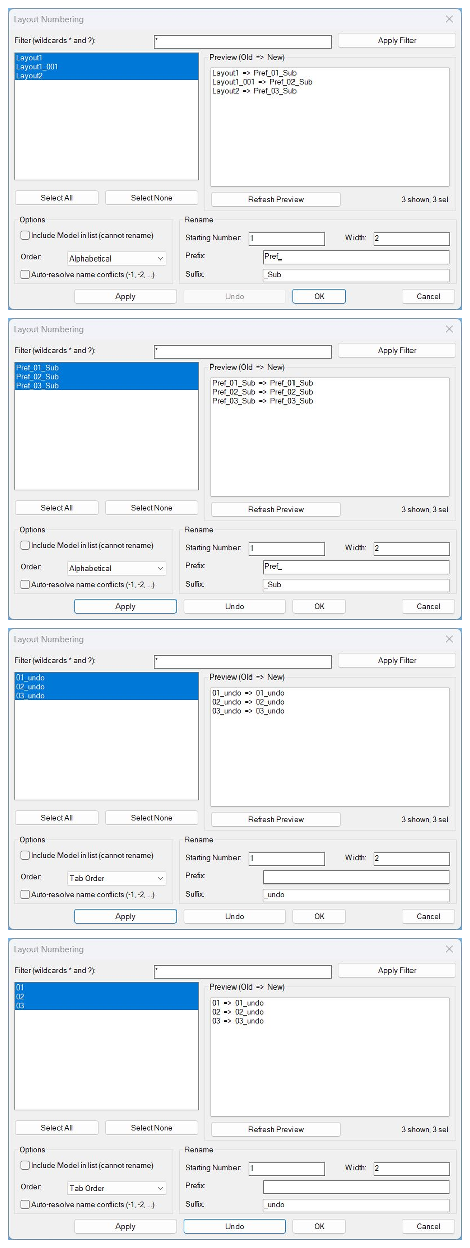
LayoutNum
🎯 The result is a controlled, preview-based layout renaming workflow for AutoCAD and Civil 3D drawings.
📑 Users can standardize sheet names, add project prefixes, apply numbered sequences, and repair layout naming order without manual tab-by-tab edits.
✅ LayoutNum improves CAD sheet organization, plotting consistency, and production drawing management.LockAllVp
✅ Faster control of viewport lock states across many layout tabs.
✅ Reduced risk of accidental viewport scale or pan changes before plotting.
✅ Clear QA overview of which layouts are fully locked, unlocked, mixed, or have no viewports.
✅ Clipboard-friendly layout/status report for checking or documenting sheet readiness.Zoom Extend
🎯 The result is a faster layout preparation workflow before plotting or publishing.
🔎 Paper space layouts can be normalized to their visible extents, reducing missed geometry and awkward zoom states.
✅ Zoom_Extend improves CAD QA for drawing packages with many sheets.Zoom Window
🎯 The result is a practical paper space zoom manager for drawings with many sheets.
🔎 Users can quickly normalize layout views or apply a consistent window zoom without manually visiting every tab.
✅ ZEZW improves plotting readiness and layout review efficiency.All_Layouts_list
✅ Fast layout name extraction from DWG files.
✅ Useful for sheet index creation, layout QA, publishing preparation, and external documentation.
✅ Reduces manual copy/paste work when drawings contain many layout tabs.
✅ Produces clean clipboard text ready for Excel, Notepad, email, or project logs.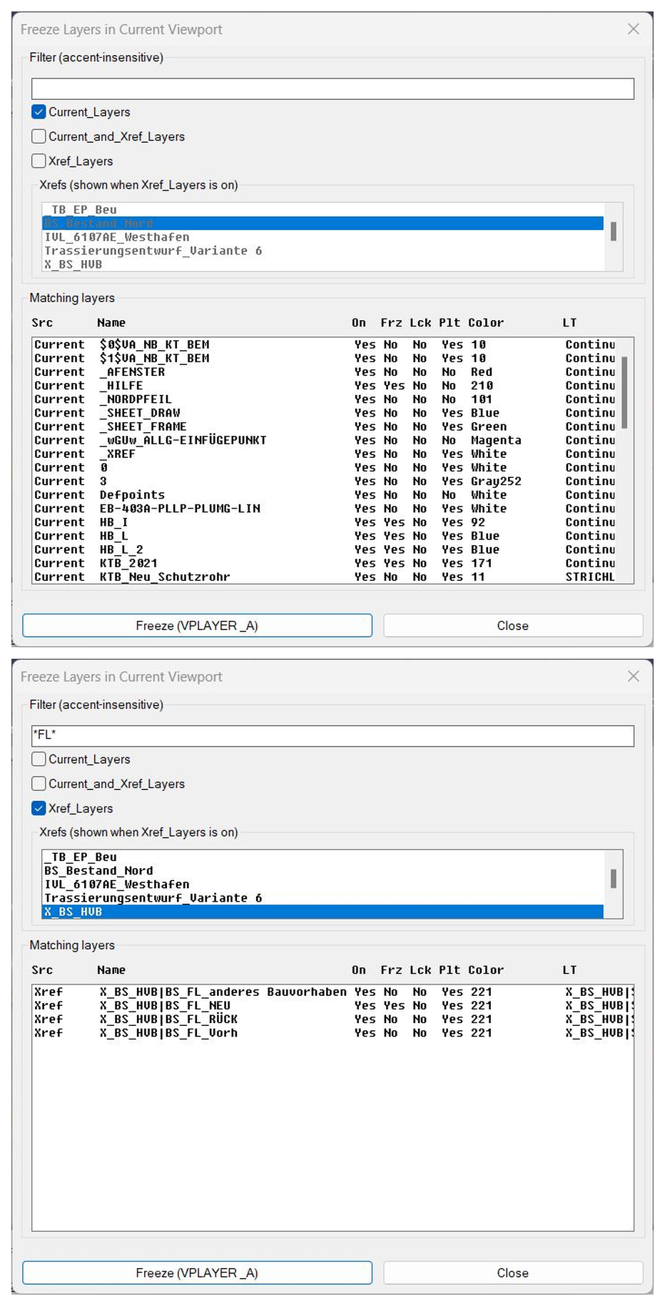
FreezeLayersInVP
🎯 The result is faster viewport layer cleanup for AutoCAD and Civil 3D paper-space workflows.
🧊 Users can isolate the exact current or xref layers they want to freeze, review their status, and apply the viewport-freeze operation from one dialog.
✅ FreezeLayersInVP improves sheet readability, xref visibility control, and layout preparation for complex production drawings.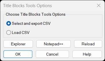
TitleBlocksTools
Result:- Main menu dialog appears with Export CSV and Load CSV options
- Selecting Export launches interactive titleblock picker and tag selector
- CSV file is generated with proper escaping and Excel-safe formatting
- CSV optionally opens in Excel automatically for editing
- Selecting Load CSV updates titleblocks from edited CSV file
- Only changed attribute values are updated (efficiency optimization)
- Single undo operation reverts all updates if needed
- Help dialog provides complete documentation with copy-to-clipboard features
- Explorer and Notepad++ buttons enable quick LISP file access and editing
- Reload button applies code changes without restarting AutoCAD
- Round-trip workflow: Export → Excel edit → Update maintains data integrity
- Status messages report counts of updated attributes and blocks
- Unicode/ASCII toggle adapts help text for different display preferences
Zoom2Layer
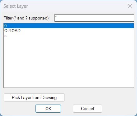
- If the user confirms a layer selection, the view zooms to the combined extents of entities on that layer.
- If no objects exist on the selected layer, prints No objects found on layer for that layer.
- If objects exist but none provide a valid bounding box, prints No valid geometry to zoom to for that layer.
- If the user cancels or no layer is selected, prints No layer selected or cancelled and performs no zoom.
RenameLayer
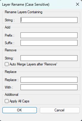
✅ The selected layers, or all currently filtered visible layers, are renamed according to the configured prefix, suffix, remove, replace, and capitalization rules.
✅ Existing destination layers can be merged automatically when Auto Merge is enabled.
✅ The drawing layer table becomes cleaner, more standardized, and easier to manage.
✅ Civil 3D and AutoCAD users can standardize large sets of layers faster than manual renaming through the Layer Properties Manager.
✅ The DCL interface preserves dialog values during filter and apply operations, making iterative rename cleanup more practical.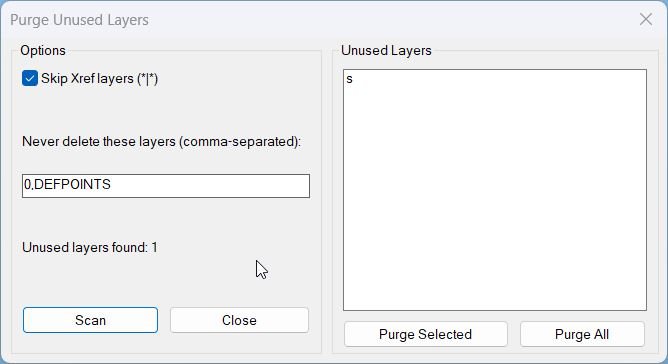
PurgeUnusedLayers
✅ Unused layers are identified and can be deleted from the active DWG.
✅ Critical layers and xref layers can be protected from accidental removal.
✅ The drawing layer table becomes cleaner for standards checking, plotting, file exchange, and template maintenance.LayersNameToClipboard
✅ Unique selected-object layer names are copied to the Windows clipboard.
✅ The output can be pasted into layer filters, Excel sheets, text reports, scripts, or project documentation.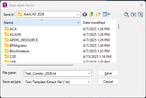
LayerList
✅ The final result is a compact AutoCAD and Civil 3D layer inventory report that helps CAD users audit DWG layer standards, review plotting configuration, diagnose frozen or locked layers, and document drawing layer properties with fewer manual steps.
By exporting the layer table to a reusable text file, LayerList improves CAD quality control, supports Excel-based reporting, speeds up project documentation, and helps maintain cleaner AutoCAD and Civil 3D production drawings.
Import_Layer_Filter
🎯 The result is a repeatable layer-filter exchange workflow for AutoCAD and Civil 3D drawings.
🟢 Layer filters can be moved from one drawing or template to another without rebuilding them manually.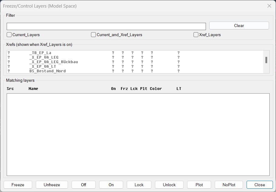
FreezeLayersInMS
🎯 The result is faster layer control inside ModelSpace, especially for drawings with many xrefs and long layer names.
🟢 Users can isolate the exact matching layers and apply visibility, locking, and plotting states without opening the full AutoCAD Layer Properties Manager.Export_Layer_Filter
🎯 The result is a portable .lft layer-filter export file that can be reused in other drawings.
🟢 Multiple filters can be exported together, reducing repetitive AutoCAD Layer Properties Manager setup work.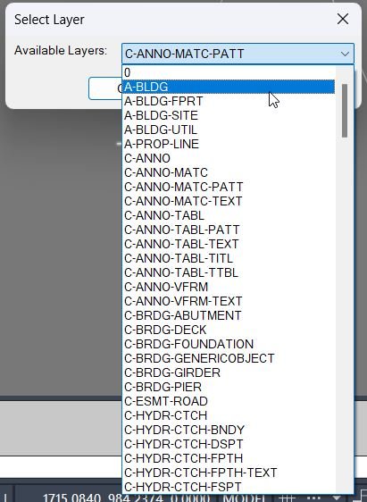
DuplicateToSelectedLayer
🎯 The result is a clean same-position duplicate set on the selected layer, useful for AutoCAD layer management and drawing production.
🟢 The command reports how many entities were duplicated and names the destination layer.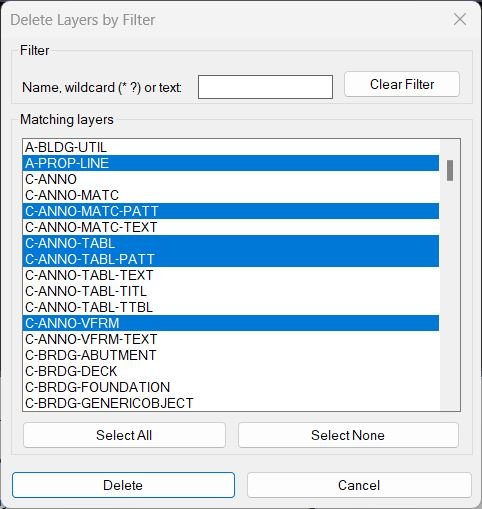
DeleteLayerByFilter
🎯 The result is a safer and faster layer cleanup workflow for AutoCAD and Civil 3D production drawings.
🧹 Users can isolate non-standard, imported, temporary, discipline-specific, or project-specific layers, export the list for review, and delete only the approved targets.
🛡️ Protected layer rules reduce the risk of deleting essential Civil 3D, xref, annotation, dimension, viewport, and default drawing layers.
📌 DeleteLayerByFilter is especially useful for cleaning consultant DWGs, external reference drawings, survey files, architecture backgrounds, structural backgrounds, and drawings with excessive unused or duplicated layer naming.Color2Llayers
🎯 The result is faster layer color editing with visual feedback, undo support, and clipboard reporting.
📊 This improves CAD layer standardization, plotting setup, layer QA/QC, and drawing cleanup in AutoCAD and Civil 3D workflows.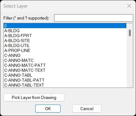
ChangeLayerToCurrent
🎯 The result is faster and safer layer reassignment with fewer manual Layer dropdown actions.
📋 The optional property-preservation mode keeps object appearance stable while still moving geometry to the selected layer.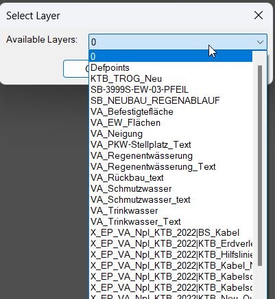
ChangeLayerToSelected
- The user chooses a target layer from a filtered popup list (optionally seeded by picking an object’s layer), and the last filter/selection are remembered for the next run.
- After confirming the layer, the user selects multiple objects and those entities are moved to the chosen layer using CHPROP.
- If the user cancels the dialog or selects no objects, no changes are made and the routine prints a cancel/no-selection message.
All_Color2Layers
🎯 The result is a cleaner AutoCAD drawing where object-level color and linetype overrides are returned to layer-driven CAD standards.
🧱 This improves layer management, plotting consistency, CAD auditing, and Civil 3D production file cleanup.SplitHatch
🎯 The result is a separated hatch structure that is easier to edit, layer-manage, delete, or isolate boundary by boundary.
🧹 The tool reduces repeated manual HATCHEDIT steps when cleaning production drawings.MleaderStraight
📌 Selected MultiLeader objects are updated with cleaner orthogonal leader-line vertices.
📊 The command prints the number of processed MultiLeaders at the command line.
🧹 Temporary DCL files and temporary XLINE objects are removed after processing.ConvertLeaderAndText2Mleader
✅ The final result is a modern MLEADER replacing the selected legacy LEADER and MTEXT pair. The old leader and text are erased, the new multileader receives the selected text content and style behavior, and the annotation becomes easier to maintain in AutoCAD or Civil 3D production drawings.
AddVertex2Mleader
✅ The result is a faster AutoCAD multileader editing workflow: the selected MLeader receives an additional vertex point, making it easier to create clean jogs, route leader lines around drawing content, and improve annotation readability.
FixLineTextOverlap
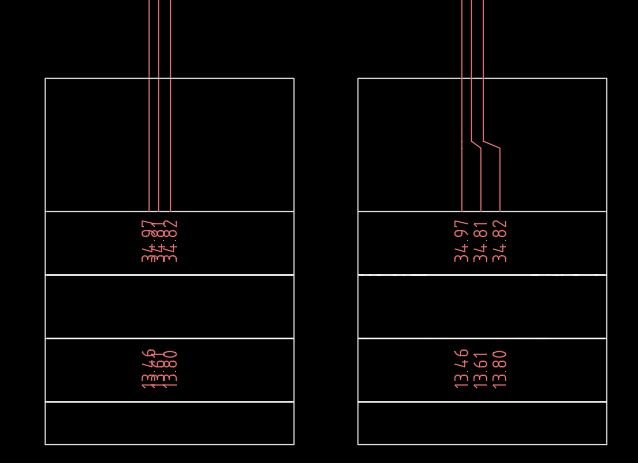
✅ The result is a cleaner AutoCAD drawing where overlapping vertical LINE entities are replaced by readable step-out polylines and related TEXT or MTEXT labels are spaced along a consistent vertical rail.
✅ The drawing becomes easier to read, easier to plot, and easier to review because linework and annotations no longer occupy the same horizontal positions.
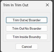
TrimIn_TrimOut_Boundary
The drawing is trimmed or cleaned according to the selected rectangular operation. Depending on the mode, the routine either leaves a visible rectangular polyline border or removes the temporary border after trimming.
NCopyExtra
The routine copies selected XREF geometry into the host AutoCAD drawing. Depending on the selected options, copied entities are either moved to _hilfslinien or assigned to clean local layer names where the XREF prefix has been removed. Layer properties can be transferred so the local drawing keeps the visual standards of the original XREF layers.
CopyMove2MidPoint
✅ The result is a precise midpoint-alignment workflow for quickly moving or copying selected AutoCAD objects from one reference location to another.
🏗️ It is useful for CAD alignment, infrastructure drafting, block/object repositioning, profile or section drafting assistance, and repeated object placement where midpoint reference control is faster than standard manual MOVE or COPY workflows.CookieCutter2
The primary routine trims intersecting drawing objects or erases visible-layer objects on the selected side of one closed boundary. It can break down blocks, hatches, and regions so their supported geometry can be processed. The multi-boundary routine preserves objects inside or crossing any selected boundary and erases objects outside the combined selected areas.

CenterAreaCentroid
📌 The result is either an AutoCAD POINT placed inside the selected closed object or a CENTROID text label placed at the geometric centroid of the selected polyline-derived region. This gives CAD users a faster way to mark internal points and centroid positions without manually calculating geometry.
TotalLengthPolyline
✅ The final result is a quick total length report for all supported selected objects. After running TLEN and selecting objects, AutoCAD displays an alert similar to: Total length of selected objects is 123.45.

TotalLengthAreaDetailed_vs_01
Result in practice • Clipboard You can immediately paste an Excel compatible formula such as =ceiling(10.25+5.75,5) into a worksheet. • Drawing annotation The routine optionally places a UCS aware MText label like 10.25+5.75=16.00 for multiple entities or just 16.00 when a single entity is selected. • Feedback Command line messages display the summed length or area with the same configured precision.TotalLengthAll
✅ After running ELEN, AutoCAD reports the number of accepted entities and their combined total length in the command line.
📌 The drawing remains unchanged because the routine only reads entity geometry and outputs a measurement summary.
TLength
✅ The result is a fast combined length value for selected AutoCAD geometry, displayed in the command line and copied to the clipboard for immediate reuse.
SumLengthField
✅ The result is a dynamic annotation workflow for AutoCAD quantity extraction.
📐 Users can place length and area totals directly in drawings, tables, labels, blocks, or leaders without manually calculating totals outside AutoCAD.
🚀 The tool improves drafting speed, quantity checking, BOQ preparation, layer-based measurement workflows, and civil engineering production documentation.PolylineArea
✅ The final result is a fast AutoCAD area-total workflow: select polylines, calculate the combined area, view the formatted result, and paste the numeric value directly into external documentation or quantity reports.
PLLengthByLayer
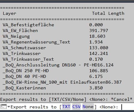
✅ Final result:
A clear AutoCAD layer-length report showing the total lightweight polyline length for each layer, with optional TXT or CSV export for documentation, quantity review, Excel processing, or project QA.LenCalc
✅ The result is a structured length report by layer, linetype, or color, delivered as an AutoCAD table, TXT file, or CSV file for CAD documentation, BOQ preparation, drawing audit, and production measurement workflows.
BookmarkEntities
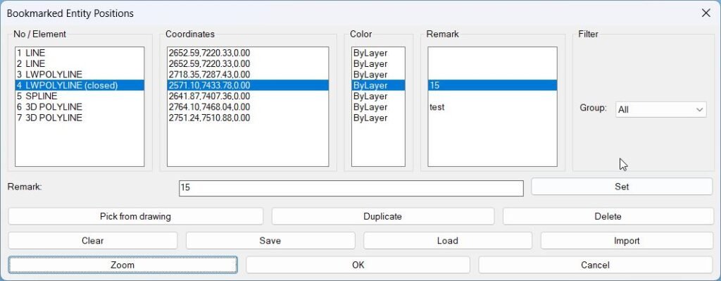
Result / Usage summary: 1. Run BMEntityPos. 2. Click “Pick from drawing”, select entities; they appear in the grid with number, type, coordinates, color, and remark column. 3. Optionally assign per-bookmark remarks (e.g., “Detail A – top left node”, “Valve 12”, etc.). 4. Use “Group” filter to quickly narrow down to Text, Polylines, Blocks… 5. Use “Zoom” to jump directly to the stored object; the tool tries to use the current geometry via handle so it works even if things moved. 6. Save the list (per drawing) and later “Load” or “Import” it again to restore your navigation points in future sessions.
In short, BMEntityPos is a lightweight bookmark & navigation manager for key entities in your DWG, complete with grouping, remarks, zooming, and per-file persistence.Exp_Imp_NamedViews
✅ The result is a repeatable AutoCAD Named Views transfer workflow. Users can save Named Views from one drawing, import them into another drawing, preserve related Visual Styles, and standardize view navigation across project DWGs without manually recreating each view.
Add_Bookmark
• Bookmark list updated — *textPositions* ends up containing one entry per processed entity in the format (label startPt endPt) • Entity count feedback — Command line reports how many entries are now stored, giving quick confirmation of captured objects • No geometry modification — The routine does not create or delete any drawing entities; it only reads and stores data • Ready for downstream tools — Other routines can later consume *textPositions* to place markers, labels, leaders, or export coordinatesClear_Bookmarks
• If OK is selected → *textPositions* is set to NIL, and a message confirms successful clearing • If Cancel is selected → Bookmark list remains intact, and a safe cancellation message is displayed • No entities or drawing data are modified, only memory storage is affected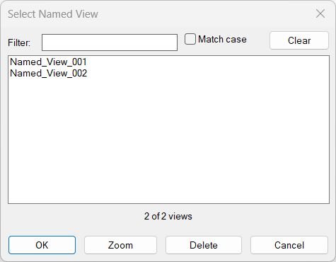
NamedViewList
✅ The result is a faster AutoCAD named view workflow. Users can audit, filter, rename, delete, zoom to, and restore saved views from one practical dialog instead of repeatedly using command-line view management.
SwapBlockAssignLayer
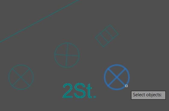
✅ Selected objects are replaced with instances of the chosen existing block, placed at each object’s insertion point or bounding-box center, while the original selected objects are removed.
RenameBlockPreview
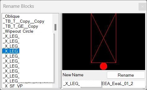
✅ The result is a faster block renaming workflow for AutoCAD and Civil 3D users. The selected block definition is renamed safely, the list refreshes after the change, and the last filter remains available for the next session.
RenameBlock
✅ The result is a faster block-renaming workflow: pick a block reference, enter the new name, and let the command rename the underlying block definition in the drawing.
DynamicBlockFilter
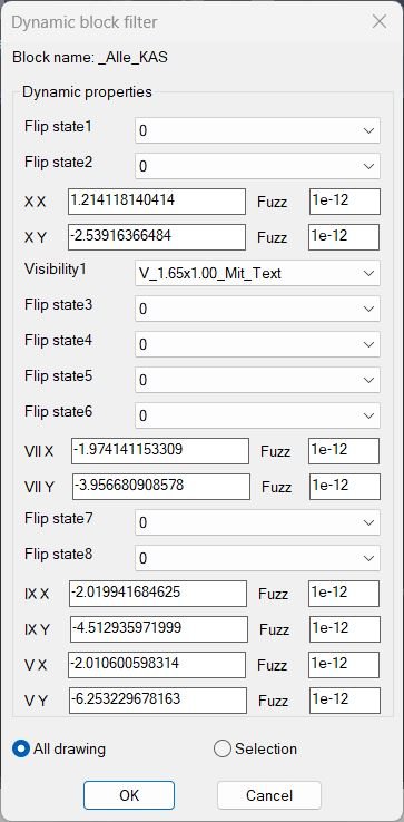
✅ The final result is a faster AutoCAD and Civil 3D dynamic block selection workflow. Instead of manually searching for block references with a specific visibility state, lookup value, distance, angle, or other dynamic property, the user selects one source block, defines matching criteria, and receives a ready-to-use AutoCAD selection set. This improves drawing cleanup, production editing, block QA, CAD standardization, and Civil 3D DWG management with fewer manual steps and more reliable filtering.
DelUnusedBlocks
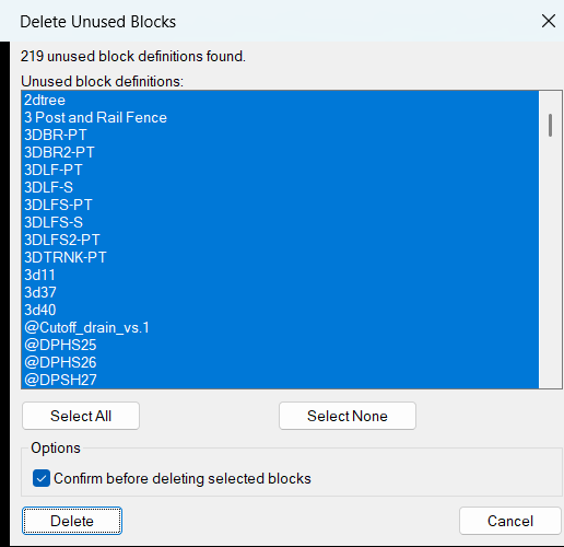
✅ The final result is a cleaner AutoCAD DWG file with selected unused block definitions removed from the drawing database.
🧹 This reduces unnecessary block table clutter, supports better CAD standards management, improves block library maintenance, and can make drawing audits, cleanup routines, and project handover workflows easier.
🚀 For AutoCAD and Civil 3D production users, DelUnusedBlocks provides a faster, more controlled alternative to manually inspecting unused blocks one by one.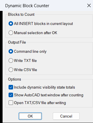
DynamicBlockCounter
✅ The final result is a fast AutoCAD and Civil 3D block quantity report that shows how many standard blocks, dynamic blocks, xrefs, and visibility-state variants exist in the current layout or selected set. The tool improves CAD productivity, drawing quality control, block library auditing, Civil 3D plan production review, quantity verification, and DWG cleanup by replacing manual block counting with a repeatable AutoLISP reporting workflow.
DelSelectBlock
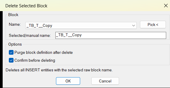
✅ The final result is a practical AutoCAD block cleanup utility that helps users remove repeated block references from a DWG faster than manual selection. It centralizes block name selection, drawing-based picking, confirmation, optional purge, saved settings, and deletion reporting in one DCL workflow. This improves CAD drafting productivity, supports cleaner drawings, reduces repetitive manual erase operations, and helps control unwanted block content in production AutoCAD files.
DeleteBlocks
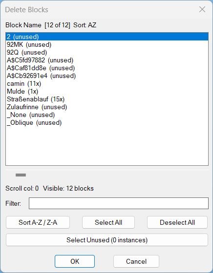
✅ The final result is a practical AutoCAD block cleanup command that centralizes block review, filtering, instance counting, unused block selection, nested block checking, and destructive block deletion in one DCL interface.
It reduces repetitive manual block cleanup work, helps users find unused or unwanted block definitions faster, improves DWG hygiene, and supports cleaner AutoCAD and Civil 3D production drawings.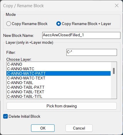
CopyBlock
Result: A new block definition is created with a new name, the chosen reference is retargeted to this definition, and optionally placed on a selected layer with its contents forced ByLayer, while the original reference can be removed automatically. • New block identity: You obtain a separate, uniquely named block that can be edited or managed independently from the original definition. • Layer controlled copy: In +Layer mode, the new block reference and its internal geometry conform to a single layer standard, improving visibility and plotting control. • Clean replacement: With “Delete Initial Block” enabled, the original reference is removed and replaced by the newly named copy in the same location. • Predictable behavior: The new block reacts as expected to layer changes and ByLayer properties, making it easier to integrate into existing layer standards. Copy code:ChangeBlockEntitiesLayer
Result: All entities inside the definitions of the selected block references are moved to the same layer as their block reference, giving full layer based control over the block content. • Consistent blocks: Internal entities no longer sit on mismatched layers, so turning the block layer on or off reliably affects the entire block content. • Easier management: Color, linetype, and plot settings can be controlled centrally from the block reference layer instead of multiple internal layers. • Global effect: Since the block definition is edited, every instance of that block in the drawing reflects the updated internal layer assignments. • Non destructive in layout: No entities are deleted or created in model or paper space, only the layer property of block definition entities is updated. Copy code:3D_PolyOffset
Short description Creates a 3D offset of a selected 3D polyline. Converts the original 3D polyline into a temporary 2D polyline. Applies a user-defined offset…
SteSysVar
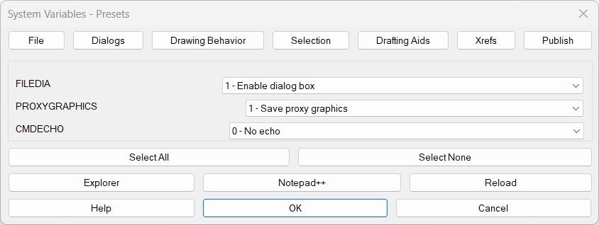
✅ The result is a faster, cleaner AutoCAD and Civil 3D setup workflow: users can review and apply multiple production-oriented system variable settings from one organized dialog instead of typing and remembering individual SETVAR values.

Hide / Show Objects
Result: Depending on the user’s choice, the drawing updates to show only selected objects, hide them, or reveal all again. Visibility attributes are updated for all entities, and the screen refreshes automatically for immediate effect.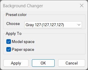
Change Background Color
Result: Model and/or Paper space background changes to the selected color preset (black, white, or gray). Cursor, tracking, and snap marker colors adjust for readability, and previous colors are restored if the dialog is canceled.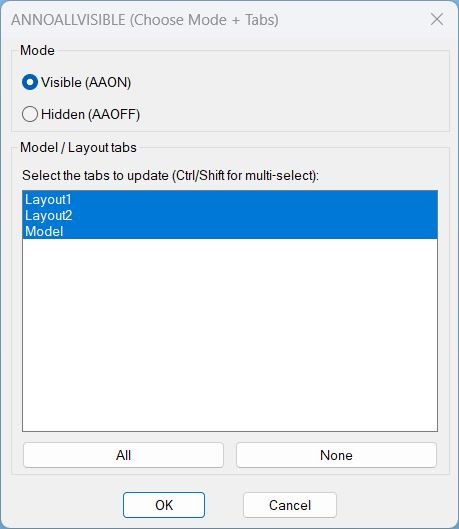
AnnoAllOnOff
🎯 The result is a controlled annotation visibility cleanup workflow for AutoCAD and Civil 3D drawings.
🔇 Users can turn off ANNOALLVISIBLE on all tabs or only selected layouts without manually switching each tab and typing the system variable.
📐 This supports plotting preparation, layout QA, annotative object cleanup, and drawing-standard workflows where visible annotation scales must be controlled per tab.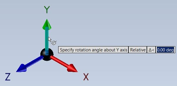
RotateUCS
Result: The current UCS is rotated around the Z axis by the angle the user specifies, the snap angle is aligned to it, and the user can store this UCS under a name to return to it later. This makes it easier to draft on rotated building wings, site orientations, or non-orthogonal geometry while keeping the cursor and ortho aligned.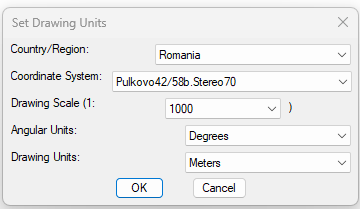
SetUpUnits
✅ The result is a faster Civil 3D drawing setup workflow where users can select a country or region, choose a coordinate system, set drawing scale, define angular units, and define drawing units from one clear AutoLISP dialog.
C3D_NamespaceFix
🎯 The result is a compact AutoCAD namespace and Visual LISP COM diagnostic report.
🧪 The user can see whether the core arithmetic symbols appear to retain normal function definitions and whether a protected multiplication test succeeds.
🔌 The report also indicates whether the AutoCAD COM access test produces an error and whether vl-load-com is present in the atom table.LayerFilterFreezeThaw
🎯 The result is a controlled layer-state update for a chosen filter group or its inverse.
🟢 The tool saves time when repeatedly isolating, hiding, thawing, or locking known project layer groups.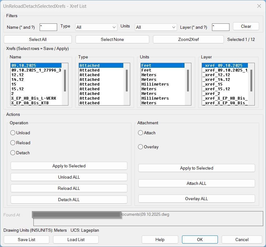
UnReloadDetachSelectedXrefs_00
Result:- Generates a reusable Xref list file containing drawing context and per-xref configuration: HOSTINSUNITS, HOSTUCSNAME, and Name|Type|FoundAt|UnitsCode|Layer lines.
- Re-applies Xref configuration deterministically to reduce unit-scaling and UCS-related inconsistencies during reload/attach workflows.
- Restores correct layer placement by forcing xref inserts onto the saved layer after load/reload actions.
- Preserves working context for bulk actions by restoring the original UCS and view after ALL operations complete.
Based on / Source code: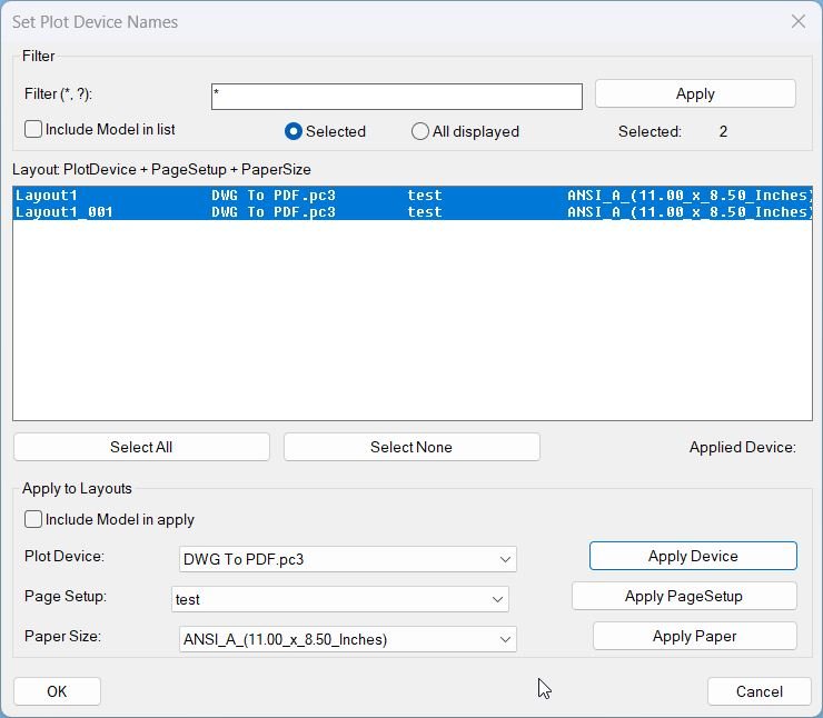
SetPlotDeviceNames_00
- All layouts that have DWG To PDF.pc3 available will have their plot device/configuration set to it.
- Any layout that does not list the device remains unchanged and is reported in the command line output.
ConvertPolylineAndText2Mleader
✅ The result is a faster AutoCAD workflow for converting existing polyline geometry into leader annotation geometry while preserving drafting properties and reducing manual redraw work.
CopyPaste2BasePoint
✅ The result is a faster and safer AutoCAD copy-paste workflow for moving geometry between drawings while keeping objects aligned to the same 0,0,0 base point.
📐 The tool reduces manual base point mistakes, supports coordinated model-space transfers, and helps maintain drawing origin consistency in production CAD environments.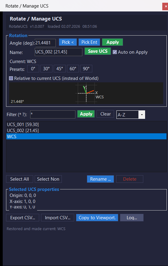
RotateUcs_vs.01
📘 The final result is a faster and more visual UCS management workflow for AutoCAD and Civil 3D. Users can rotate the UCS by typed angle, picked angle, or selected entity angle, save and restore named UCS records, preview UCS orientation, highlight selected UCS axes in the drawing, export and import UCS definitions, copy UCS settings into layout viewports, and review detailed logs. This improves productivity, reduces repetitive UCS command-line work, supports cleaner viewport orientation control, and helps CAD teams manage drawing navigation and drafting orientation with fewer manual steps.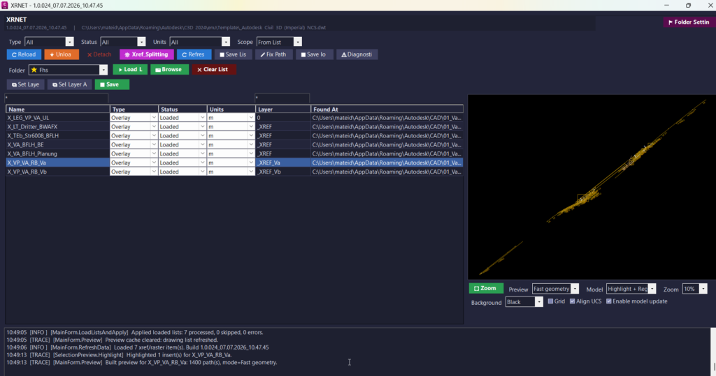
UnReloadDetachSelectedXrefs_vs.02
✅ The final result is a productivity-focused AutoCAD and Civil 3D xref management plugin that centralizes DWG xrefs, raster images, file paths, reference status, preview, export, diagnostics, and cleanup actions in one interface. It reduces repetitive manual work, improves external reference quality control, helps detect missing or incorrect paths, supports faster project setup, improves drawing organization, and gives CAD users a more reliable workflow for managing complex Civil 3D and AutoCAD drawings.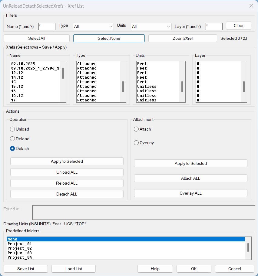
UnReloadDetachSelectedXrefs_01
Result Running UnReloadDetachSelectedXrefs opens a dialog where the user can safely batch-manage xrefs without manually selecting drawing entities. The user can unload, reload, or detach xrefs, convert attach type between Attached and Overlay, zoom to xref inserts, and save or load repeatable xref lists. Saved lists are plain text and can be reused to recreate or standardize xref setups, including layer assignment and units control during attach operations. Tags Lisp, Xrefs, Dialog_UI, DCL, Layers, UCS, WCS, Coordinate_Systems, Model Space Suggest relevant tags not in the above list File_IO, Batch_Processing, Path_Management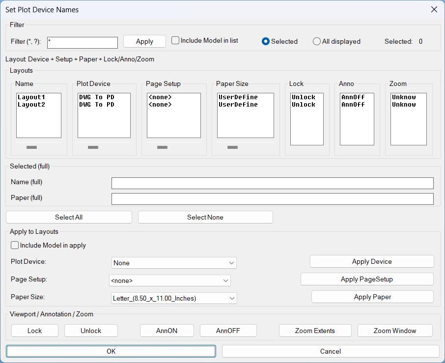
SetPublishLocation_01
Result- User can quickly standardize plotting configuration per layout, then verify lock, annotation visibility, and zoom status at a glance inside one dialog.
- Important behavior: Zoom status shows ZExt only when applied by Zoom Extents, otherwise it shows Z question mark.
- Tags: CAD, Lisp, Plot, Layouts, Paper Space, Viewports, DCL, Dialog_UI, Plot_Device, Page_Setup, Paper_Size, General_AutoCAD.
- Suggested tags not in provided list: Batch_Apply, Viewport_Lock, Annotation_Visibility, Zoom_Tools, Plot_Standardization.
DuplicateLayouts_01
Tags- Layouts, DCL, Dialog_UI, General_AutoCAD, Extra_AutoCAD, Lisp
- Undo or UndoMark grouping
- Naming or UniqueName generation
- Batch duplication workflow
CreatesXrefsLayersAssign_01
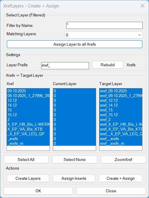
Result- Standardizes XREF organization by enabling consistent per-XREF target layers using a prefix strategy.
- Provides a fast way to force all XREFs onto a single existing layer for audits, plotting, or temporary coordination workflows.
- Improves visibility with a live Current Layer column and synchronized selections across all lists.
- Prevents silent failures by safely handling locked layers during reassignment.
- Accelerates navigation with ZoomXref using precise ActiveX ZoomWindow extents.
Slope_01
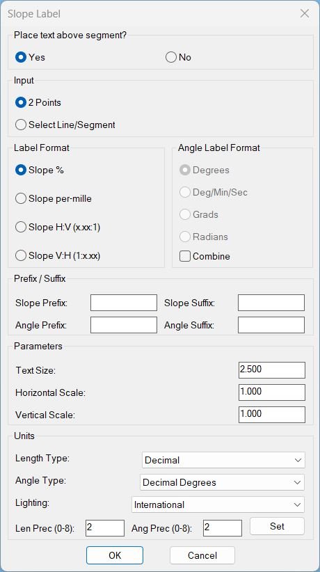
Result / Output: • Geometry: One MTEXT entity per labeled segment (or per 2-point pair), placed at the segment midpoint, offset a fixed distance along the normal, rotated to match the segment angle. • Text content: Formatted slope string (with prefix/suffix) and, if enabled, a line break followed by the formatted angle string. • Visual style: Uses the current text style, current layer, and the user-selected text height & width factor for consistent appearance in the drawing. • User feedback: Command line messages confirm each created label and indicate when invalid or zero-length segments are skipped. Overall, running slope_p produces clear, customizable slope/angle MTEXT annotations along your design geometry with minimal repetitive work.Slope_00
• Precise slope labels — TEXT entities created at midpoint, rotated along slope line • Formatted exactly as selected — %, H:V, V:H, H:V decimal, or V:H decimal • Correct sign & scaling — Reflects positive or negative slope and custom scaling factors • Safe & consistent — Covers extreme cases (vertical/horizontal) with stable output • Reusable workflow — Settings persist per session, enabling repetitive point-pair labeling with consistencyCloseParalelPolylines
• Geometric result Produces one polyline formed from the two originals plus two connectors • Drawing cleanup Converts parallel or open shapes into a single clean polyline ready for editing • Environment safety All system variables restored to previous values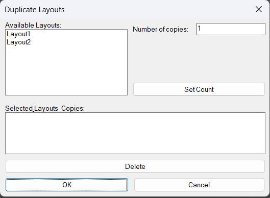
DuplicateLayouts_00
- If the user clicks OK, each selected layout is duplicated the specified number of times and new layouts are created with incremented suffix names.
- If the user cancels, no layouts are duplicated and the routine exits after removing the temporary DCL file.
- Always unloads the dialog and deletes the generated DCL file after closing the UI.
- If the dialog fails to load, prints DCL failed. and exits without changes.
DB_Planung_Gelände
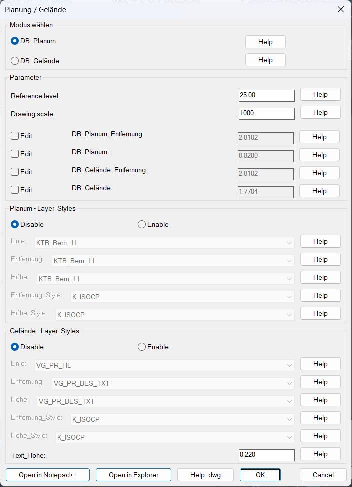
Result: After configuring and running the tool, your drawing gains Planum or Gelaende profile labels that show distance and elevation at chosen points along the band, using consistent layers, text styles, and offsets defined in the dialog. • Consistent annotation: All generated leader lines and texts follow a unified standard for layers, styles, color, text height, and numeric formatting across the project. • Saved project settings: The INI file keeps the last used mode and values so subsequent runs in the same drawing start with familiar, project specific defaults instead of factory defaults. • Guided workflow: Users see graphical help and clear dialog structure, making it easier to configure complex Planum and Gelaende labeling without manually editing many system variables or layer properties. • Clean environment: System variables, view states, and temporary layer color changes are restored at the end, and the tool leaves the drawing in a predictable state ready for further work. Copy code: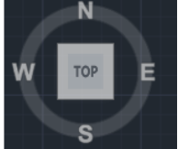
CubeDisplay_Off_On
Result: After running the command, the Navigation Cube will reappear on screen, fully refreshed and responsive. This is especially helpful when the cube becomes invisible after workspace changes, viewport switching, or 3D navigation glitches.Page Tag: 🏷️ Autocad Lisps – status