
Short description
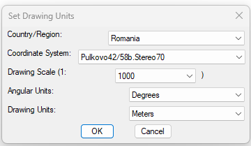
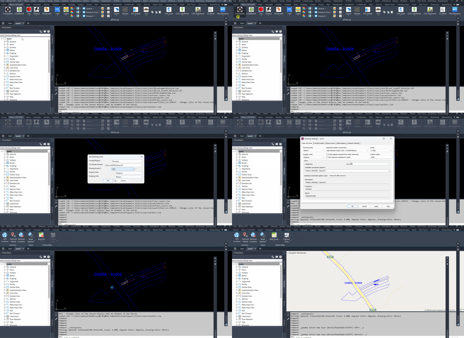
🌍 SetUpUnits is a Civil 3D AutoLISP utility for setting drawing units, coordinate systems, drawing scale, and angular units from one dialog.
🚩 It includes a country and region selector with live flag preview, making coordinate system selection faster and easier for CAD and Civil 3D production drawings.
Command:
🚀 Main command defined in the uploaded code: SETTUPUNITS
🧰 Main settings routine: setunits
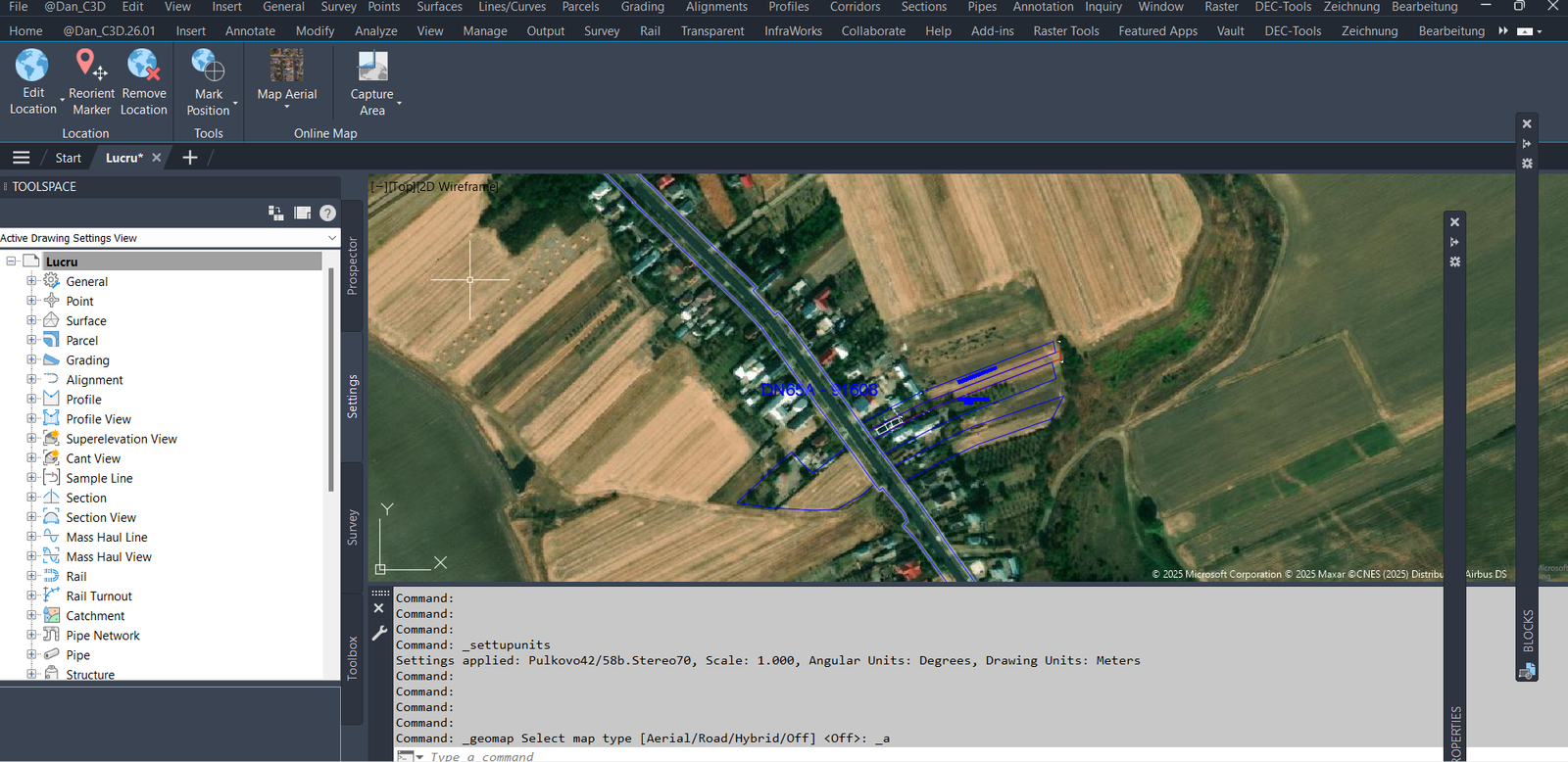
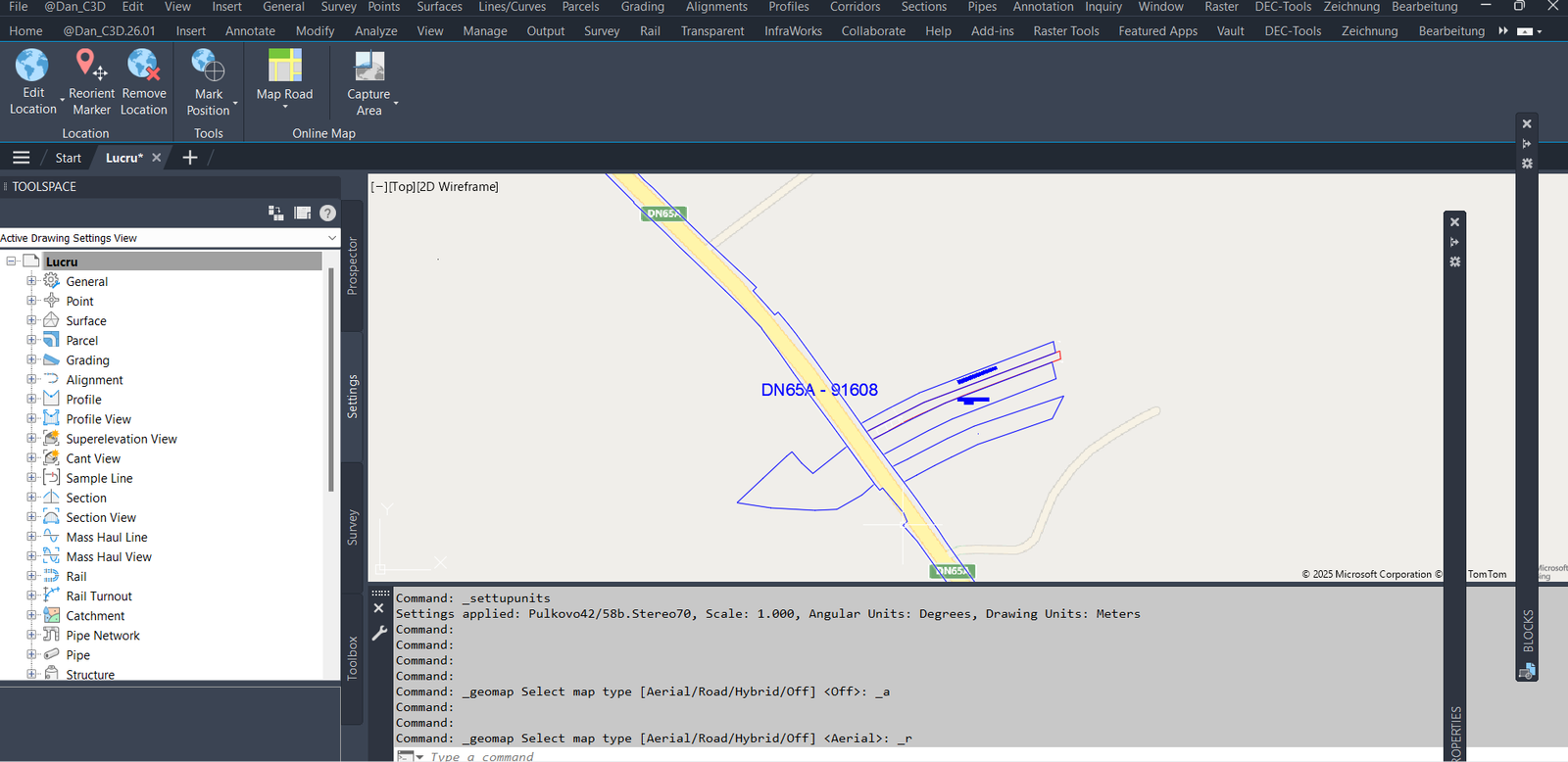
📐 Civil 3D drawing settings updated: coordinate system code, drawing scale, angular units, and drawing units.
Description:
📘 SetUpUnits is an SEO-friendly Civil 3D AutoLISP command that centralizes drawing unit setup, coordinate system selection, and drawing scale configuration in a generated DCL dialog.
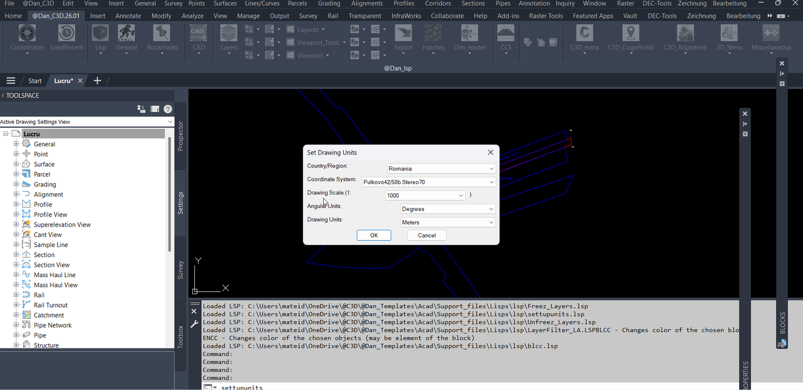
🌍 The routine displays a country or region list, updates the available coordinate system codes for the selected location, and shows a live flag preview beside the selector. This helps Civil 3D users choose coordinate settings more clearly when working with international projects, UTM systems, national grid systems, and local drawing standards.
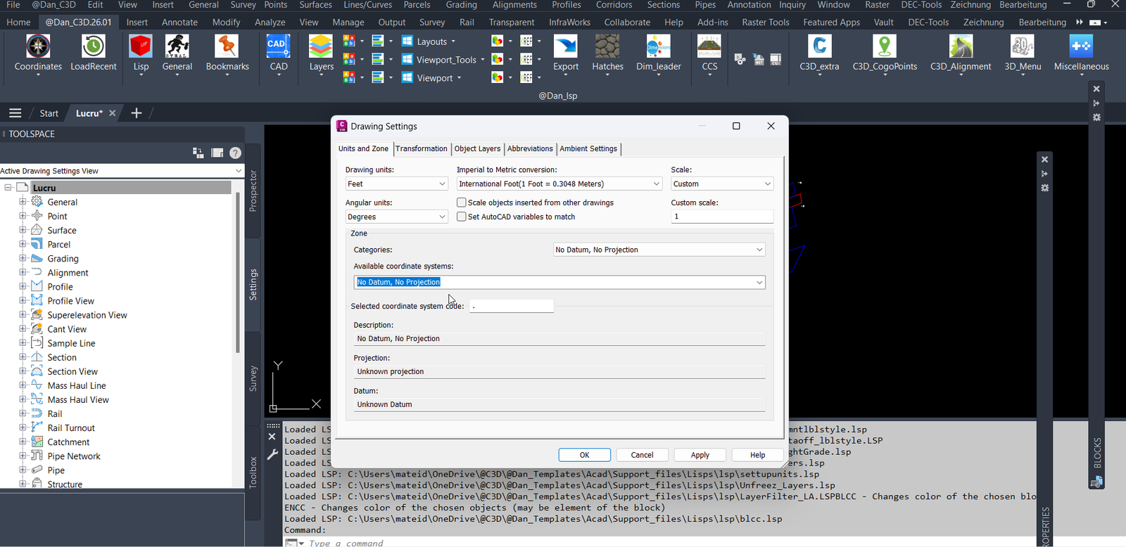
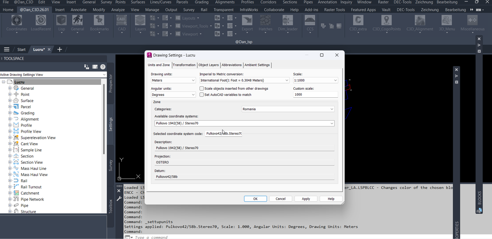
📐 After the user accepts the dialog, the program connects to the Civil 3D Land application object and writes the selected settings into the active drawing’s unit zone settings. It updates the Civil 3D coordinate system code, drawing scale, angular units, and drawing units through Aecc COM automation.
🚩 The flag preview is loaded on demand from external country flag data files. RGB pixel values are mapped to AutoCAD ACI colors and drawn into the DCL image tile using optimized run-length fill_image calls.
🧭 This tool is useful for CAD managers, Civil 3D designers, survey teams, roadway engineers, infrastructure projects, template maintenance, and drawing setup workflows where coordinate systems and units must be applied consistently.
Helper function: (if any)
🧩 setunits writes Civil 3D drawing settings using AeccXUiLand application automation, ActiveDocument, DrawingSettings, UnitZoneSettings, and CoordinateSystem properties.
🔎 getaeccApp reads the installed Civil 3D release from the AutoCAD registry product key and creates the correct Aecc application interface object.
🎨 rgb->aci converts external RGB flag pixel values to the nearest AutoCAD Color Index so the DCL preview can be rendered with AutoCAD image tile colors.
📁 flag-data-file builds the external path to the matching flag _data.lsp file using FLAGS_ROOT and the first letter subfolder.
🚩 draw_flag loads the country pixel list on demand, scales it to the DCL image tile, and uses run-length grouping to reduce fill_image calls.
🔄 update_zones refreshes the coordinate system list and the flag preview whenever the country or region selection changes.
Functionalities:
[‘🌍 Opens a country and region based Civil 3D drawing setup dialog.’, ‘🗺️ Lists coordinate system codes for the selected country, region, UTM group, or world coordinate system category.’, ‘🚩 Shows a live flag preview in the DCL dialog using external flag pixel data.’, ‘📐 Lets the user select drawing scale values such as 1, 20, 50, 100, 200, 500, 1000, 2000, and 5000.’, ‘📏 Lets the user choose drawing units including feet, meters, millimeters, centimeters, decimeters, and inches.’, ‘🧭 Lets the user choose angular units including degrees, radians, and grads.’, ‘🔧 Applies the chosen Civil 3D coordinate system code to the active drawing.’, ‘⚙️ Applies drawing scale, angular unit mode, and drawing unit mode through Civil 3D COM settings.’, ‘🇷🇴 Starts with Romania, scale 1000, degrees, and meters as the default dialog selections in the uploaded code.’, ‘🧰 Generates the DCL dialog at runtime in the AutoCAD temporary folder and deletes it after use.’, ‘🎨 Converts RGB flag data to AutoCAD ACI colors for DCL image rendering.’, ‘⚡ Uses run-length encoding logic so consecutive same-color pixels are drawn efficiently.’, ‘📌 Prints the applied coordinate system, scale, angular unit, and drawing unit result to the AutoCAD command line.’]
Result:
✅ The result is a faster Civil 3D drawing setup workflow where users can select a country or region, choose a coordinate system, set drawing scale, define angular units, and define drawing units from one clear AutoLISP dialog.
Images, animations etc.
XAML code:
<ResourceDictionary
xmlns="http://schemas.microsoft.com/winfx/2006/xaml/presentation"
xmlns:x="http://schemas.microsoft.com/winfx/2006/xaml"
xmlns:src="clr-namespace:Autodesk.Windows;assembly=AdWindows">
<src:RibbonToolTip x:Key="SetUpUnits">
<src:RibbonToolTip.ExpandedContent>
<StackPanel>
<TextBlock Background="AntiqueWhite" TextAlignment="Left">
<Bold>Function Syntax: SetUpUnits</Bold>
<LineBreak/>
<Bold>Version: 1 Date: 05.08.2025</Bold>
<LineBreak/>
<LineBreak/>
<Hyperlink>N/A</Hyperlink>
<LineBreak/>
<Bold><Run Foreground="DodgerBlue">Function Syntax: SetUpUnits</Run></Bold><LineBreak/>
<Bold><Run Foreground="DodgerBlue">Command:</Run></Bold> <Bold><Run Foreground="Orange">SETTUPUNITS</Run></Bold><LineBreak/>
<LineBreak/>
<Bold><Run Foreground="DodgerBlue">Description</Run></Bold><LineBreak/>
<Run Foreground="White">🌍 SetUpUnits is a Civil 3D AutoLISP utility for setting drawing units, coordinate systems, drawing scale, and angular units from one dialog.</Run><LineBreak/>
<Run Foreground="LimeGreen">It helps CAD and Civil 3D users apply consistent project setup standards faster, especially when working with national grids, UTM zones, international coordinate systems, and template-based production drawings.</Run><LineBreak/>
<LineBreak/>
<Bold><Run Foreground="DodgerBlue">Main Command</Run></Bold><LineBreak/>
<Run Foreground="White">🚀 Run </Run><Bold><Run Foreground="Orange">SETTUPUNITS</Run></Bold><Run Foreground="White"> in the AutoCAD or Civil 3D command line to open the Set Drawing Units dialog.</Run><LineBreak/>
<Run Foreground="White">🧰 The uploaded code defines the command as </Run><Bold><Run Foreground="Orange">c:settupunits</Run></Bold><Run Foreground="White"> and uses the helper routine </Run><Bold><Run Foreground="Orange">setunits</Run></Bold><Run Foreground="White"> to apply the selected settings.</Run><LineBreak/>
<LineBreak/>
<Bold><Run Foreground="DodgerBlue">SEO Optimized Description</Run></Bold><LineBreak/>
<Run Foreground="White">📘 This Civil 3D drawing setup tool centralizes coordinate system selection, drawing unit configuration, drawing scale setup, and angular unit setup in one generated DCL interface.</Run><LineBreak/>
<Run Foreground="White">🌍 The dialog includes a country and region selector, a coordinate system dropdown, a drawing scale dropdown, an angular units dropdown, and a drawing units dropdown.</Run><LineBreak/>
<Run Foreground="White">🚩 When a country or region changes, the tool refreshes the coordinate system list and draws a live flag preview from external flag data files.</Run><LineBreak/>
<Run Foreground="White">📐 The selected Civil 3D coordinate system code, scale, angular units, and drawing units are written to the active drawing through Civil 3D Aecc COM settings.</Run><LineBreak/>
<Run Foreground="White">🧠 This is useful for CAD managers, Civil 3D designers, survey teams, roadway engineers, infrastructure design offices, drawing template maintenance, and standardized project setup workflows.</Run><LineBreak/>
<LineBreak/>
<Bold><Run Foreground="LimeGreen">Functionalities</Run></Bold><LineBreak/>
<Run Foreground="White">🌍 </Run><Bold><Run Foreground="LimeGreen">Country and region based setup</Run></Bold><Run Foreground="White"> - lists coordinate systems by country, region, UTM group, world system, or custom coordinate category.</Run><LineBreak/>
<Run Foreground="White">🗺️ </Run><Bold><Run Foreground="LimeGreen">Coordinate system selection</Run></Bold><Run Foreground="White"> - fills the coordinate system dropdown from the embedded </Run><Bold><Run Foreground="Orange">zoneDB</Run></Bold><Run Foreground="White"> database.</Run><LineBreak/>
<Run Foreground="White">🚩 </Run><Bold><Run Foreground="LimeGreen">Live flag preview</Run></Bold><Run Foreground="White"> - loads country flag pixel data from external </Run><Bold><Run Foreground="Orange">_data.lsp</Run></Bold><Run Foreground="White"> files and renders it in the DCL image tile.</Run><LineBreak/>
<Run Foreground="White">📐 </Run><Bold><Run Foreground="LimeGreen">Drawing scale setup</Run></Bold><Run Foreground="White"> - supports common scale display choices such as </Run><Bold><Run Foreground="Orange">1</Run></Bold><Run Foreground="White">, </Run><Bold><Run Foreground="Orange">20</Run></Bold><Run Foreground="White">, </Run><Bold><Run Foreground="Orange">50</Run></Bold><Run Foreground="White">, </Run><Bold><Run Foreground="Orange">100</Run></Bold><Run Foreground="White">, </Run><Bold><Run Foreground="Orange">200</Run></Bold><Run Foreground="White">, </Run><Bold><Run Foreground="Orange">500</Run></Bold><Run Foreground="White">, </Run><Bold><Run Foreground="Orange">1000</Run></Bold><Run Foreground="White">, </Run><Bold><Run Foreground="Orange">2000</Run></Bold><Run Foreground="White">, and </Run><Bold><Run Foreground="Orange">5000</Run></Bold><Run Foreground="White">.</Run><LineBreak/>
<Run Foreground="White">📏 </Run><Bold><Run Foreground="LimeGreen">Drawing unit setup</Run></Bold><Run Foreground="White"> - allows feet, meters, millimeters, centimeters, decimeters, and inches.</Run><LineBreak/>
<Run Foreground="White">🧭 </Run><Bold><Run Foreground="LimeGreen">Angular unit setup</Run></Bold><Run Foreground="White"> - allows degrees, radians, and grads.</Run><LineBreak/>
<Run Foreground="White">🔧 </Run><Bold><Run Foreground="LimeGreen">Civil 3D settings write-back</Run></Bold><Run Foreground="White"> - updates </Run><Bold><Run Foreground="Orange">UnitZoneSettings</Run></Bold><Run Foreground="White"> and </Run><Bold><Run Foreground="Orange">CoordinateSystem</Run></Bold><Run Foreground="White"> properties in the active Civil 3D drawing.</Run><LineBreak/>
<Run Foreground="White">🇷🇴 </Run><Bold><Run Foreground="LimeGreen">Practical default setup</Run></Bold><Run Foreground="White"> - starts with Romania, scale 1000, degrees, and meters in the uploaded code.</Run><LineBreak/>
<Run Foreground="White">🎨 </Run><Bold><Run Foreground="LimeGreen">RGB to AutoCAD color conversion</Run></Bold><Run Foreground="White"> - maps flag RGB values to nearest ACI colors for DCL image drawing.</Run><LineBreak/>
<Run Foreground="White">⚡ </Run><Bold><Run Foreground="LimeGreen">Optimized image drawing</Run></Bold><Run Foreground="White"> - groups consecutive same-color pixels so the flag preview is drawn with fewer </Run><Bold><Run Foreground="Orange">fill_image</Run></Bold><Run Foreground="White"> calls.</Run><LineBreak/>
<LineBreak/>
<Bold><Run Foreground="DodgerBlue">Key Internal Functions</Run></Bold><LineBreak/>
<Run Foreground="White">🧩 </Run><Bold><Run Foreground="Orange">setunits</Run></Bold><Run Foreground="White"> applies the selected coordinate system, drawing scale, angular units, and drawing units to the active Civil 3D document.</Run><LineBreak/>
<Run Foreground="White">🔎 </Run><Bold><Run Foreground="Orange">getaeccApp</Run></Bold><Run Foreground="White"> detects the Civil 3D release and creates the matching Aecc application interface.</Run><LineBreak/>
<Run Foreground="White">🎨 </Run><Bold><Run Foreground="Orange">rgb->aci</Run></Bold><Run Foreground="White"> converts RGB color values to AutoCAD Color Index values.</Run><LineBreak/>
<Run Foreground="White">📁 </Run><Bold><Run Foreground="Orange">flag-data-file</Run></Bold><Run Foreground="White"> builds the external file path for each country flag data file.</Run><LineBreak/>
<Run Foreground="White">🚩 </Run><Bold><Run Foreground="Orange">draw_flag</Run></Bold><Run Foreground="White"> loads and draws the flag preview in the DCL image tile.</Run><LineBreak/>
<Run Foreground="White">🔄 </Run><Bold><Run Foreground="Orange">update_zones</Run></Bold><Run Foreground="White"> refreshes the coordinate system dropdown and updates the flag preview when the country changes.</Run><LineBreak/>
<LineBreak/>
<Bold><Run Foreground="DodgerBlue">Practical Result</Run></Bold><LineBreak/>
<Run Foreground="White">✅ The result is a faster Civil 3D drawing setup workflow for applying coordinate systems, drawing scale, drawing units, and angular units from one visual interface.</Run><LineBreak/>
<Run Foreground="LimeGreen">This improves CAD standards control, Civil 3D template preparation, survey drawing setup, infrastructure design consistency, and project startup efficiency.</Run><LineBreak/>
<LineBreak/>
<Bold><Run Foreground="DarkRed">Important Notes</Run></Bold><LineBreak/>
<Run Foreground="White">⚠️ This tool depends on Civil 3D Aecc COM interfaces and is intended for Civil 3D environments.</Run><LineBreak/>
<Run Foreground="White">⚠️ The live flag preview depends on the hard-coded </Run><Bold><Run Foreground="Orange">FLAGS_ROOT</Run></Bold><Run Foreground="White"> folder and external flag </Run><Bold><Run Foreground="Orange">_data.lsp</Run></Bold><Run Foreground="White"> files.</Run><LineBreak/>
<Run Foreground="White">⚠️ The embedded coordinate system database should be maintained carefully when adding or modifying coordinate codes.</Run><LineBreak/>
<LineBreak/>
<Bold><Run Foreground="Gold">Tags</Run></Bold><LineBreak/>
<Run Foreground="Yellow">🏷️ AutoCAD</Run><LineBreak/>
<Run Foreground="Yellow">🏷️ Civil 3D</Run><LineBreak/>
<Run Foreground="Yellow">🏷️ AutoLISP</Run><LineBreak/>
<Run Foreground="Yellow">🏷️ DCL Dialog</Run><LineBreak/>
<Run Foreground="Yellow">🏷️ Coordinate System</Run><LineBreak/>
<Run Foreground="Yellow">🏷️ Drawing Units</Run><LineBreak/>
<Run Foreground="Yellow">🏷️ Drawing Scale</Run><LineBreak/>
<Run Foreground="Yellow">🏷️ Unit Zone Settings</Run><LineBreak/>
<Run Foreground="Yellow">🏷️ Aecc COM Automation</Run><LineBreak/>
<Run Foreground="Yellow">🏷️ Civil 3D Settings</Run><LineBreak/>
<Run Foreground="Yellow">🏷️ Country Selector</Run><LineBreak/>
<Run Foreground="Yellow">🏷️ Flag Preview</Run><LineBreak/>
<Run Foreground="Yellow">🏷️ UTM Coordinate Systems</Run><LineBreak/>
<Run Foreground="Yellow">🏷️ Survey Setup</Run><LineBreak/>
<Run Foreground="Yellow">🏷️ CAD Standards</Run><LineBreak/>
<Run Foreground="Yellow">🏷️ Infrastructure Design</Run><LineBreak/>
<Run Foreground="Yellow">🏷️ Drawing Template</Run><LineBreak/>
<Run Foreground="Yellow">🏷️ Production Workflow</Run><LineBreak/>
<Run Foreground="Yellow">🏷️ SETTUPUNITS</Run><LineBreak/>
</TextBlock>
<Grid>
<MediaElement
Source="SetUpUnits.gif"
Stretch="Uniform"
Visibility="Visible"/>
</Grid>
<Grid>
<Image Source="Image_000.png" Stretch="Uniform"/>
</Grid>
<Grid>
<Image Source="Image_001.png" Stretch="Uniform"/>
</Grid>
<Grid>
<Image Source="Image_002.png" Stretch="Uniform"/>
</Grid>
<Grid>
<Image Source="Image_003.png" Stretch="Uniform"/>
</Grid>
<Grid>
<Image Source="Image_004.png" Stretch="Uniform"/>
</Grid>
<Grid>
<Image Source="Image_005.png" Stretch="Uniform"/>
</Grid>
</StackPanel>
</src:RibbonToolTip.ExpandedContent>
</src:RibbonToolTip>
</ResourceDictionary>
Leave a Reply
You must be logged in to post a comment.