
Short description
📐 AutoCAD AutoLISP tool for creating profile offsets from existing entities with native OFFSET behavior, 30 degree branch continuation, and design reconstruction existing layer modes.
Command:
30PARAEXIST / PARA30EXIST
Description:
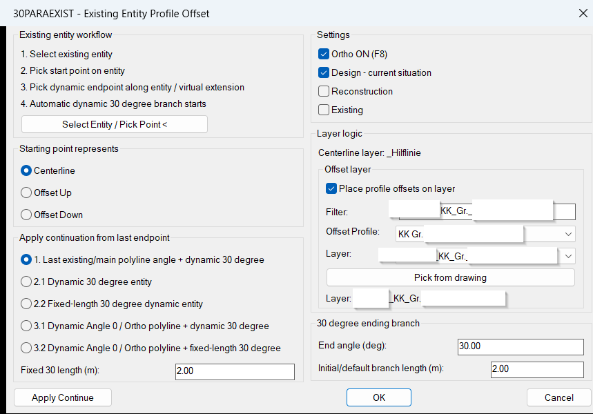
📘 30ParallelExisting builds civil utility profile geometry from an existing AutoCAD entity. It uses selected-entity following, native OFFSET behavior, Profile_002 profile presets, centerline and offset route management, dynamic 30 degree branches, full-route offset rebuilds, Apply continuation modes, and design reconstruction existing layer logic for Civil 3D production drawings.
Helper function: (if any)
Functionalities:
• 🚀 Runs with the 30PARAEXIST and PARA30EXIST command aliases.
• 📌 Starts from an existing line or curve, with pick-point fallback where needed.
• 📐 Creates automatic profile offsets from selected geometry using AutoCAD offset logic.
• 🧱 Supports Profile_002 profile presets and profile-based offset distances.
• 🔀 Supports centerline, offset up, and offset down start references.
• 🧭 Adds automatic dynamic or fixed-length 30 degree branch continuations.
• 🔄 Provides Apply continuation modes including last-angle plus 30, dynamic 30, fixed 30, Ortho plus dynamic 30, and Ortho plus fixed 30.
• 🟡 Supports Design, Reconstruction, and Existing layer modes.
• 🎯 Uses visible temporary preview entities during dynamic placement.
• 🧹 Rebuilds offsets from the complete centerline after continuation so offset branches remain parallel.
Result:
✅ Produces existing-geometry-based utility routes with centerline, offset profiles, branch continuations, and layer logic for Civil 3D and AutoCAD infrastructure design workflows.
Images, animations etc.
XAML code:
<ResourceDictionary
xmlns="http://schemas.microsoft.com/winfx/2006/xaml/presentation"
xmlns:x="http://schemas.microsoft.com/winfx/2006/xaml"
xmlns:src="clr-namespace:Autodesk.Windows;assembly=AdWindows">

<src:RibbonToolTip x:Key="30ParallelExisting">
<src:RibbonToolTip.ExpandedContent>
<StackPanel>
<TextBlock Background="AntiqueWhite" TextAlignment="Left">
<Bold>Function Syntax: 30paraexist / para30exist</Bold>
<LineBreak/>
<Bold>Version: 1.0 Date: 27.06.2026 13:51:27</Bold>
<LineBreak/>

<Bold>30paraexist</Bold> <LineBreak/> <Run>The </Run><Bold>30paraexist</Bold><Run> command creates a KK profile connection from an already existing AutoCAD entity and continues it with dynamic 30 degree or orthogonal continuation segments.</Run> <LineBreak/> <Run>The command is designed for existing line/polyline based geometry. The selected entity is used as the reference path, including its existing vertices and direction. The profile offsets are generated from this existing path and can then be continued dynamically.</Run> <LineBreak/>
<Bold>Command Names</Bold> <LineBreak/> <Run>Command: </Run><Bold>30PARAEXIST</Bold> <LineBreak/> <Run>Alias: </Run><Bold>PARA30EXIST</Bold> <LineBreak/>
<Bold>Main Functionality</Bold> <LineBreak/> <Run> Select an existing entity to use as the reference path.</Run> <LineBreak/> <Run> Pick a start point on the selected entity.</Run> <LineBreak/> <Run> Move the mouse along the selected entity to choose the endpoint dynamically.</Run> <LineBreak/> <Run> The centerline and both KK offset sides are previewed dynamically during endpoint selection.</Run> <LineBreak/> <Run> After the existing-entity profile run is placed, a dynamic 30 degree branch starts automatically.</Run> <LineBreak/> <Run> The 30 degree branch endpoint is dynamic. Moving the mouse controls the branch side and length.</Run> <LineBreak/> <Run> Offset sides are joined with chamfered / mitered transitions at the connection point.</Run> <LineBreak/> <Run> The final result is drawn as joined profile polylines, not separated broken offset segments.</Run> <LineBreak/>
<Bold>DCL Dialog Areas</Bold> <LineBreak/>
<Bold>Profile Area</Bold> <LineBreak/> <Run>Selects the KK profile type and profile offset dimensions used for both sides of the route.</Run> <LineBreak/> <Run>The selected profile controls the left and right offset distance from the centerline.</Run> <LineBreak/>
<Bold>Starting Point Represents</Bold> <LineBreak/> <Run>This option defines what the picked reference entity represents.</Run> <LineBreak/> <Run> </Run><Bold>Centerline</Bold><Run>  the selected existing entity is treated as the centerline.</Run> <LineBreak/> <Run> </Run><Bold>Offset Up</Bold><Run>  the selected existing entity is treated as the upper offset edge. The internal centerline is shifted automatically from that offset.</Run> <LineBreak/> <Run> </Run><Bold>Offset Down</Bold><Run>  the selected existing entity is treated as the lower offset edge. The internal centerline is shifted automatically from that offset.</Run> <LineBreak/> <Run>This is important when the existing drawing geometry is not the centerline but one of the profile edges.</Run> <LineBreak/>
<Bold>Select Entity / Start-End Points Area</Bold> <LineBreak/> <Run>The </Run><Bold>Select Entity / Start-End Points <</Bold><Run> button starts the main placement workflow.</Run> <LineBreak/> <Run>First, select the existing reference entity. Then pick the start point on that entity. After that, move the mouse along the entity and click the endpoint. A dynamic preview shows the profile path before placement.</Run> <LineBreak/>
<Bold>30 Degree Branch Area</Bold> <LineBreak/> <Run>After the existing-entity profile run is placed, the command automatically starts the 30 degree dynamic branch.</Run> <LineBreak/> <Run>The mouse position controls the branch side and branch length. Clicking places the branch. Pressing ESC during this step ends after the existing-entity offset part.</Run> <LineBreak/>
<Bold>End Angle</Bold> <LineBreak/> <Run>Defines the branch angle used for the automatic ending branch. The default value is </Run><Bold>30</Bold><Run> degrees.</Run> <LineBreak/>
<Bold>Fixed 30 Length</Bold> <LineBreak/> <Run>Defines the fixed length used by fixed-length 30 degree continuation modes. The default value is </Run><Bold>2.00 m</Bold><Run>.</Run> <LineBreak/> <Run>Even when the length is fixed, the side selection remains dynamic. Moving the mouse chooses the direction side before clicking to place.</Run> <LineBreak/>
<Bold>Apply Continuation Area</Bold> <LineBreak/> <Run>After one route has been created, the dialog opens again. Clicking </Run><Bold>Apply Continue</Bold><Run> continues from the last endpoint.</Run> <LineBreak/> <Run>Clicking </Run><Bold>OK</Bold><Run> ends the command.</Run> <LineBreak/>
<Bold>Apply Continuation Modes</Bold> <LineBreak/> <Run> </Run><Bold>1. Last polyline angle + dynamic 30 degree</Bold> <LineBreak/> <Run>Continues first with the last existing/main polyline angle, then starts a dynamic 30 degree branch.</Run> <LineBreak/> <Run>This means the continuation begins in the last route direction, not immediately with another 30 degree branch.</Run> <LineBreak/>
<Run> </Run><Bold>2.1 Dynamic 30 degree entity</Bold> <LineBreak/> <Run>Starts a dynamic 30 degree continuation directly from the last endpoint.</Run> <LineBreak/> <Run>The mouse controls the 30 degree side and the length.</Run> <LineBreak/>
<Run> </Run><Bold>2.2 Fixed-length 30 degree entity</Bold> <LineBreak/> <Run>Starts a 30 degree continuation with a predefined fixed length.</Run> <LineBreak/> <Run>The length comes from the </Run><Bold>Fixed 30 Length</Bold><Run> field, but the side selection is still dynamic.</Run> <LineBreak/>
<Run> </Run><Bold>3.1 Angle 0 / Ortho polyline + dynamic 30 degree</Bold> <LineBreak/> <Run>Continues first with an Angle 0 / Ortho dynamic polyline segment, then starts a dynamic 30 degree branch.</Run> <LineBreak/> <Run>The first orthogonal part is shown dynamically with profile offsets before placement.</Run> <LineBreak/>
<Run> </Run><Bold>3.2 Angle 0 / Ortho polyline + fixed-length 30 degree</Bold> <LineBreak/> <Run>Continues first with an Angle 0 / Ortho dynamic polyline segment, then starts a fixed-length 30 degree branch.</Run> <LineBreak/> <Run>The 30 degree branch uses the fixed length field, while the branch side remains dynamic.</Run> <LineBreak/>
<Bold>Layer Logic</Bold> <LineBreak/> <Run>The centerline is drawn on the helper centerline layer, typically </Run><Bold>_Hilflinie</Bold><Run>.</Run> <LineBreak/> <Run>The KK offset profile lines are drawn on the selected offset/profile layer.</Run> <LineBreak/> <Run>Layers matching </Run><Bold>VA_KTB_KK*</Bold><Run> are handled as KK layers and use AutoCAD color </Run><Bold>11</Bold><Run>.</Run> <LineBreak/>
<Bold>Ortho Option</Bold> <LineBreak/> <Run>The dialog includes an </Run><Bold>Ortho ON</Bold><Run> option.</Run> <LineBreak/> <Run>When enabled, orthogonal continuation steps follow the configured orthogonal direction while still keeping the profile offsets and chamfered transitions.</Run> <LineBreak/>
<Bold>Profile Dimensions</Bold> <LineBreak/> <Run>The command uses the selected KK profile to determine the profile offset distance.</Run> <LineBreak/> <Run>Typical profiles include:</Run> <LineBreak/> <Run> KK Gr. I i.F_220X275  offset 0.110 / 0.110</Run> <LineBreak/> <Run> KK Gr. II i.F_400X275  offset 0.200 / 0.200</Run> <LineBreak/> <Run> KK Gr. IIIa i.F_515X275  offset 0.2575 / 0.2575</Run> <LineBreak/> <Run> KK Gr. IV i.F_700X285  offset 0.350 / 0.350</Run> <LineBreak/>
<Bold>Typical Workflow</Bold> <LineBreak/> <Run>1. Run </Run><Bold>30PARAEXIST</Bold><Run>.</Run> <LineBreak/> <Run>2. Select the required KK profile and start reference mode.</Run> <LineBreak/> <Run>3. Click </Run><Bold>Select Entity / Start-End Points <</Bold><Run>.</Run> <LineBreak/> <Run>4. Select the existing reference entity.</Run> <LineBreak/> <Run>5. Pick the start point on the entity.</Run> <LineBreak/> <Run>6. Move the mouse along the entity and click the endpoint.</Run> <LineBreak/> <Run>7. Move the mouse to choose the 30 degree branch side and length.</Run> <LineBreak/> <Run>8. Click to place the 30 degree branch.</Run> <LineBreak/> <Run>9. Use </Run><Bold>Apply Continue</Bold><Run> to continue from the last endpoint, or click </Run><Bold>OK</Bold><Run> to finish.</Run> <LineBreak/>
<Bold>Result</Bold> <LineBreak/> <Run>The command creates a joined KK profile route from an existing entity, with dynamic endpoint selection, automatic 30 degree continuation, optional Apply-based continuation modes, correct start reference handling, and chamfered profile offset transitions.</Run>


<LineBreak/>
<Hyperlink>N/A</Hyperlink>
<LineBreak/>
</TextBlock>

<Grid>
<Image Source="Image_000.png" Stretch="Uniform"/>
</Grid>

</StackPanel>
</src:RibbonToolTip.ExpandedContent>
</src:RibbonToolTip>


<src:RibbonToolTip x:Key="30ParallelExisting_1.0">
<src:RibbonToolTip.ExpandedContent>
<StackPanel>
<TextBlock Background="AntiqueWhite" TextAlignment="Left">
<Bold>Function Syntax: 30paraexist / para30exist</Bold>
<LineBreak/>
<Bold>Version: 1.0 Date: 27.06.2026 13:51:27</Bold>
<LineBreak/>
<Bold>Version: 1.1 Date: 02.07.2026 10:44:24AM</Bold>
<LineBreak/>

<Bold>30paraexist</Bold> <LineBreak/> <Run>The </Run><Bold>30paraexist</Bold><Run> command creates a KK profile connection from an already existing AutoCAD entity and continues it with dynamic 30 degree or orthogonal continuation segments.</Run> <LineBreak/> <Run>The command is designed for existing line/polyline based geometry. The selected entity is used as the reference path, including its existing vertices and direction. The profile offsets are generated from this existing path and can then be continued dynamically.</Run> <LineBreak/>
<Bold>Command Names</Bold> <LineBreak/> <Run>Command: </Run><Bold>30PARAEXIST</Bold> <LineBreak/> <Run>Alias: </Run><Bold>PARA30EXIST</Bold> <LineBreak/>
<Bold>Main Functionality</Bold> <LineBreak/> <Run> Select an existing entity to use as the reference path.</Run> <LineBreak/> <Run> Pick a start point on the selected entity.</Run> <LineBreak/> <Run> Move the mouse along the selected entity to choose the endpoint dynamically.</Run> <LineBreak/> <Run> The centerline and both KK offset sides are previewed dynamically during endpoint selection.</Run> <LineBreak/> <Run> After the existing-entity profile run is placed, a dynamic 30 degree branch starts automatically.</Run> <LineBreak/> <Run> The 30 degree branch endpoint is dynamic. Moving the mouse controls the branch side and length.</Run> <LineBreak/> <Run> Offset sides are joined with chamfered / mitered transitions at the connection point.</Run> <LineBreak/> <Run> The final result is drawn as joined profile polylines, not separated broken offset segments.</Run> <LineBreak/>
<Bold>DCL Dialog Areas</Bold> <LineBreak/>
<Bold>Profile Area</Bold> <LineBreak/> <Run>Selects the KK profile type and profile offset dimensions used for both sides of the route.</Run> <LineBreak/> <Run>The selected profile controls the left and right offset distance from the centerline.</Run> <LineBreak/>
<Bold>Starting Point Represents</Bold> <LineBreak/> <Run>This option defines what the picked reference entity represents.</Run> <LineBreak/> <Run> </Run><Bold>Centerline</Bold><Run>  the selected existing entity is treated as the centerline.</Run> <LineBreak/> <Run> </Run><Bold>Offset Up</Bold><Run>  the selected existing entity is treated as the upper offset edge. The internal centerline is shifted automatically from that offset.</Run> <LineBreak/> <Run> </Run><Bold>Offset Down</Bold><Run>  the selected existing entity is treated as the lower offset edge. The internal centerline is shifted automatically from that offset.</Run> <LineBreak/> <Run>This is important when the existing drawing geometry is not the centerline but one of the profile edges.</Run> <LineBreak/>
<Bold>Select Entity / Start-End Points Area</Bold> <LineBreak/> <Run>The </Run><Bold>Select Entity / Start-End Points <</Bold><Run> button starts the main placement workflow.</Run> <LineBreak/> <Run>First, select the existing reference entity. Then pick the start point on that entity. After that, move the mouse along the entity and click the endpoint. A dynamic preview shows the profile path before placement.</Run> <LineBreak/>
<Bold>30 Degree Branch Area</Bold> <LineBreak/> <Run>After the existing-entity profile run is placed, the command automatically starts the 30 degree dynamic branch.</Run> <LineBreak/> <Run>The mouse position controls the branch side and branch length. Clicking places the branch. Pressing ESC during this step ends after the existing-entity offset part.</Run> <LineBreak/>
<Bold>End Angle</Bold> <LineBreak/> <Run>Defines the branch angle used for the automatic ending branch. The default value is </Run><Bold>30</Bold><Run> degrees.</Run> <LineBreak/>
<Bold>Fixed 30 Length</Bold> <LineBreak/> <Run>Defines the fixed length used by fixed-length 30 degree continuation modes. The default value is </Run><Bold>2.00 m</Bold><Run>.</Run> <LineBreak/> <Run>Even when the length is fixed, the side selection remains dynamic. Moving the mouse chooses the direction side before clicking to place.</Run> <LineBreak/>
<Bold>Apply Continuation Area</Bold> <LineBreak/> <Run>After one route has been created, the dialog opens again. Clicking </Run><Bold>Apply Continue</Bold><Run> continues from the last endpoint.</Run> <LineBreak/> <Run>Clicking </Run><Bold>OK</Bold><Run> ends the command.</Run> <LineBreak/>
<Bold>Apply Continuation Modes</Bold> <LineBreak/> <Run> </Run><Bold>1. Last polyline angle + dynamic 30 degree</Bold> <LineBreak/> <Run>Continues first with the last existing/main polyline angle, then starts a dynamic 30 degree branch.</Run> <LineBreak/> <Run>This means the continuation begins in the last route direction, not immediately with another 30 degree branch.</Run> <LineBreak/>
<Run> </Run><Bold>2.1 Dynamic 30 degree entity</Bold> <LineBreak/> <Run>Starts a dynamic 30 degree continuation directly from the last endpoint.</Run> <LineBreak/> <Run>The mouse controls the 30 degree side and the length.</Run> <LineBreak/>
<Run> </Run><Bold>2.2 Fixed-length 30 degree entity</Bold> <LineBreak/> <Run>Starts a 30 degree continuation with a predefined fixed length.</Run> <LineBreak/> <Run>The length comes from the </Run><Bold>Fixed 30 Length</Bold><Run> field, but the side selection is still dynamic.</Run> <LineBreak/>
<Run> </Run><Bold>3.1 Angle 0 / Ortho polyline + dynamic 30 degree</Bold> <LineBreak/> <Run>Continues first with an Angle 0 / Ortho dynamic polyline segment, then starts a dynamic 30 degree branch.</Run> <LineBreak/> <Run>The first orthogonal part is shown dynamically with profile offsets before placement.</Run> <LineBreak/>
<Run> </Run><Bold>3.2 Angle 0 / Ortho polyline + fixed-length 30 degree</Bold> <LineBreak/> <Run>Continues first with an Angle 0 / Ortho dynamic polyline segment, then starts a fixed-length 30 degree branch.</Run> <LineBreak/> <Run>The 30 degree branch uses the fixed length field, while the branch side remains dynamic.</Run> <LineBreak/>
<Bold>Layer Logic</Bold> <LineBreak/> <Run>The centerline is drawn on the helper centerline layer, typically </Run><Bold>_Hilflinie</Bold><Run>.</Run> <LineBreak/> <Run>The KK offset profile lines are drawn on the selected offset/profile layer.</Run> <LineBreak/> <Run>Layers matching </Run><Bold>VA_KTB_KK*</Bold><Run> are handled as KK layers and use AutoCAD color </Run><Bold>11</Bold><Run>.</Run> <LineBreak/>
<Bold>Ortho Option</Bold> <LineBreak/> <Run>The dialog includes an </Run><Bold>Ortho ON</Bold><Run> option.</Run> <LineBreak/> <Run>When enabled, orthogonal continuation steps follow the configured orthogonal direction while still keeping the profile offsets and chamfered transitions.</Run> <LineBreak/>
<Bold>Profile Dimensions</Bold> <LineBreak/> <Run>The command uses the selected KK profile to determine the profile offset distance.</Run> <LineBreak/> <Run>Typical profiles include:</Run> <LineBreak/> <Run> KK Gr. I i.F_220X275  offset 0.110 / 0.110</Run> <LineBreak/> <Run> KK Gr. II i.F_400X275  offset 0.200 / 0.200</Run> <LineBreak/> <Run> KK Gr. IIIa i.F_515X275  offset 0.2575 / 0.2575</Run> <LineBreak/> <Run> KK Gr. IV i.F_700X285  offset 0.350 / 0.350</Run> <LineBreak/>
<Bold>Typical Workflow</Bold> <LineBreak/> <Run>1. Run </Run><Bold>30PARAEXIST</Bold><Run>.</Run> <LineBreak/> <Run>2. Select the required KK profile and start reference mode.</Run> <LineBreak/> <Run>3. Click </Run><Bold>Select Entity / Start-End Points <</Bold><Run>.</Run> <LineBreak/> <Run>4. Select the existing reference entity.</Run> <LineBreak/> <Run>5. Pick the start point on the entity.</Run> <LineBreak/> <Run>6. Move the mouse along the entity and click the endpoint.</Run> <LineBreak/> <Run>7. Move the mouse to choose the 30 degree branch side and length.</Run> <LineBreak/> <Run>8. Click to place the 30 degree branch.</Run> <LineBreak/> <Run>9. Use </Run><Bold>Apply Continue</Bold><Run> to continue from the last endpoint, or click </Run><Bold>OK</Bold><Run> to finish.</Run> <LineBreak/>
<Bold>Result</Bold> <LineBreak/> <Run>The command creates a joined KK profile route from an existing entity, with dynamic endpoint selection, automatic 30 degree continuation, optional Apply-based continuation modes, correct start reference handling, and chamfered profile offset transitions.</Run>


<LineBreak/>
<Hyperlink>N/A</Hyperlink>
<LineBreak/>
</TextBlock>

<Grid>
<Image Source="Image_000.png" Stretch="Uniform"/>
</Grid>

</StackPanel>
</src:RibbonToolTip.ExpandedContent>
</src:RibbonToolTip>


</ResourceDictionary>