
Short description
Sort / Purpose:
Interactive slope-label placement tool for linework in Civil 3D / AutoCAD.
• Type of tool: Dialog-driven annotation command that creates MTEXT labels.
• Scope: Works on picked point pairs or on every segment of selected LINE / LWPOLYLINE / POLYLINE entities.
• Goal: Quickly place readable slope (and optional angle) labels with user-controlled format, prefixes/suffixes and scaling.
Command:
Command name: SLOPE_P
Entry: Type slope_p in the command line and press Enter.
Description:
What this command does:
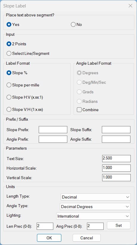
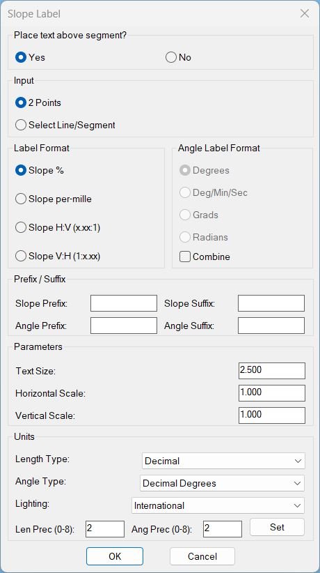
Opens a “Slope Label” dialog where you define label style (slope format, angle format, text size, horizontal/vertical scale, prefixes/suffixes, units).
After confirming, you choose between two workflows:
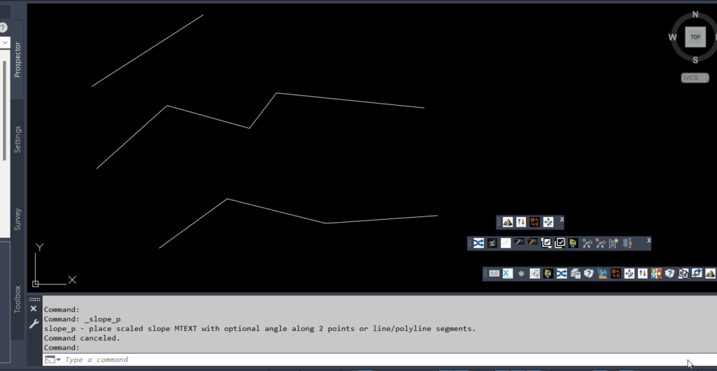
• 2 Points mode: Repeatedly pick point pairs; each pair gets a slope (and optional angle) MTEXT label at the midpoint, offset above/below the segment.
• Select Line/Segment mode: Select one or many LINE/LWPOLYLINE/POLYLINE entities; every individual segment gets a label.
Helper function: (if any)
Main helper functions used by c:slope_p:
• PLTXT-MAKE-DCL – Builds the temporary DCL dialog definition file for the Slope Label UI.
• SPU-ParseInt / SPU-GetLightingUnits / SPU-SetLightingUnits – Small utilities to read integers safely and sync dialog “Units / Lighting” with drawing variables.
• SPU_UpdateAngEnable – Enables/disables the angle-format radio buttons when “Combine” is toggled.
• SPU_SetUnits – Applies all unit-related settings (LUNITS, AUNITS, LIGHTINGUNITS, precisions) from the dialog to the drawing.
• PLTXT-GetVertices / PLTXT-GetSegListFromEntity – Extract vertices and build per-segment (p0,p1) lists from LINE / LWPOLYLINE / POLYLINE entities.
• PLTXT-READ-VALUES – Reads text height, H-scale, V-scale and all prefix/suffix strings from the dialog and stores them in globals.
• PLTXT-AngToString – Converts an angle (radians) into formatted text according to the chosen angle format (deg, dms, grad, rad) and AUPREC.
• PLTXT-SHOW-DIALOG – Drives the dialog lifecycle: initializes tiles from current globals, wires all actions, and returns OK/Cancel result.
• PLTXT-CREATE-MTEXT – Core geometry/annotation engine: computes slope, text content, offset direction, and creates the MTEXT entity for one segment.
• PLTXT-Loop-2Pts – Implements the “2 Points” picking loop and calls PLTXT-CREATE-MTEXT for each pair.
• PLTXT-Loop-Ent – Implements the “Select Line/Segment” loop; for each selected entity it builds segment lists and calls PLTXT-CREATE-MTEXT on each.
Functionalities:
Key functionalities of slope_p:
• Dual input modes: 2-point mode or entity-selection mode, switchable in the dialog.
• Flexible slope formats: Percentage, per-mille, H:V ratio (x.xx:1), or V:H ratio (1:x.xx).
• Optional angle label: Can show angle in Degrees, DMS, Grads, or Radians; may be combined on a second line under the slope.
• Prefix / Suffix control: Independent prefix/suffix strings for slope and angle text (e.g., “S=” or “α=” etc.).
• Scaling & offset: User-set text height, horizontal/vertical scale factors (to respect vertical exaggeration), and above/below toggle for label offset from the line.
• Drawing units integration: Dialog can read and set LUNITS, AUNITS, LIGHTINGUNITS, and their precisions for consistent numeric formatting.
• Segment-wise labeling: For polylines, every segment is processed individually with its own midpoint and orientation.
• Robust checks: Skips zero-length segments, handles vertical slopes (INF) and guards against invalid numeric inputs.
Result:
Result / Output:
• Geometry: One MTEXT entity per labeled segment (or per 2-point pair), placed at the segment midpoint, offset a fixed distance along the normal, rotated to match the segment angle.
• Text content: Formatted slope string (with prefix/suffix) and, if enabled, a line break followed by the formatted angle string.
• Visual style: Uses the current text style, current layer, and the user-selected text height & width factor for consistent appearance in the drawing.
• User feedback: Command line messages confirm each created label and indicate when invalid or zero-length segments are skipped.
Overall, running slope_p produces clear, customizable slope/angle MTEXT annotations along your design geometry with minimal repetitive work.
Images, animations etc.
Log in to download.
Log in
Log in
Additional info:
Based on / Source code:
Open Website
Leave a Reply
You must be logged in to post a comment.