
Short description
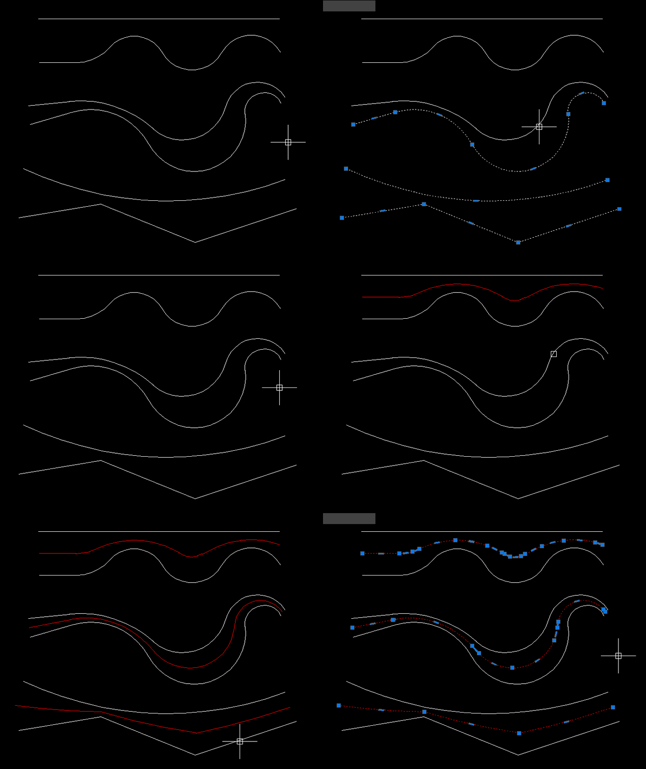
🧩 MiddleLinePolylines provides the CPL command for creating a centerline between two selected open AutoCAD curves.
📐 The current version accepts general open vlax curve objects such as LINE LWPOLYLINE POLYLINE SPLINE and ARC rather than only polylines.
🧠 The algorithm uses temporary curve copies offsets lofted geometry and geometric intersection processing to derive the middle path.
Command:
Main command: CPL
Description:
🖱️ The user selects a first and second open curve and the picked sides help determine the temporary offset directions.
🌐 Selected curves are copied with VLA Copy so general supported curve types can be processed.
📏 A working offset distance is calculated from the maximum distance relationship between the two curves.
🏗️ The routine creates temporary offsets and lofts geometry from each source copy toward its offset.
🎯 Intersection style processing is then used to derive the center path.
📐 The source reports a polyline result for straight geometry and a spline result when curves are present.
🛡️ Elevation normal UCS view and AutoCAD version checks are included.
↩️ Temporary system variables are restored through the command error handler and undo group.
Helper function: (if any)
MaxDist calculates separation between selected curve geometry.
check_offset validates temporary offset creation.
check_elev and check_normal validate source curve compatibility.
check_ET check_ucs check_view and check_ver perform environment checks.
Functionalities:
✅ Two curve centerline – creates a middle path between two selected open curves.
✅ General open curve support – uses vlax curve validation for line polyline spline arc and similar objects.
✅ Automatic working offset – calculates a construction offset from curve separation.
✅ Temporary source copies – protects original curves during the construction process.
✅ Loft based processing – uses AutoCAD LOFT geometry as part of the centerline algorithm.
✅ Straight result handling – can produce polyline centerline geometry.
✅ Curved result handling – can produce spline centerline geometry.
✅ Elevation validation – checks selected curve elevation compatibility.
✅ Normal validation – checks source object orientation compatibility.
✅ UCS and view validation – includes environment checks before geometric processing.
Result:
🎯 The result is a centerline between the two selected open curves.
📐 The resulting entity can be a polyline for straight source geometry or a spline when curved geometry requires it.
Images, animations etc.
XAML code:
<ResourceDictionary
    xmlns="http://schemas.microsoft.com/winfx/2006/xaml/presentation"
    xmlns:x="http://schemas.microsoft.com/winfx/2006/xaml"
    xmlns:src="clr-namespace:Autodesk.Windows;assembly=AdWindows">

    <src:RibbonToolTip x:Key="centerPline">
        <src:RibbonToolTip.ExpandedContent>
            <StackPanel>
                <TextBlock Background="AntiqueWhite" TextAlignment="Left">
				<Bold>Function Syntax: CPL</Bold>
<LineBreak/>
<Bold>Version: 1.0 Date: 20.06.2026 6:38:59PM</Bold>
				<LineBreak/>
				<Hyperlink>website: https://www.cadtutor.net/forum/topic/49702-centerline-between-two-polylines/</Hyperlink>
				<LineBreak/>

<Bold><Run Foreground="DodgerBlue">Description</Run></Bold><LineBreak/>
<Run Foreground="White">🧩 MiddleLinePolylines provides the CPL command for creating a centerline between two selected open AutoCAD curves.</Run><LineBreak/>
<Run Foreground="White">📐 The current version accepts general open vlax curve objects such as LINE LWPOLYLINE POLYLINE SPLINE and ARC rather than only polylines.</Run><LineBreak/>
<Run Foreground="White">🧠 The algorithm uses temporary curve copies offsets lofted geometry and geometric intersection processing to derive the middle path.</Run><LineBreak/>
<LineBreak/>
<Bold><Run Foreground="DodgerBlue">Function Syntax</Run></Bold><LineBreak/>
<Run Foreground="White">Main command: </Run><Bold><Run Foreground="Orange">CPL</Run></Bold><LineBreak/>
<LineBreak/>
<Bold><Run Foreground="DodgerBlue">SEO Optimized Overview</Run></Bold><LineBreak/>
<Run Foreground="White">🖱️ The user selects a first and second open curve and the picked sides help determine the temporary offset directions.</Run><LineBreak/>
<Run Foreground="White">🌐 Selected curves are copied with VLA Copy so general supported curve types can be processed.</Run><LineBreak/>
<Run Foreground="White">📏 A working offset distance is calculated from the maximum distance relationship between the two curves.</Run><LineBreak/>
<Run Foreground="White">🏗️ The routine creates temporary offsets and lofts geometry from each source copy toward its offset.</Run><LineBreak/>
<Run Foreground="White">🎯 Intersection style processing is then used to derive the center path.</Run><LineBreak/>
<Run Foreground="White">📐 The source reports a polyline result for straight geometry and a spline result when curves are present.</Run><LineBreak/>
<Run Foreground="White">🛡️ Elevation normal UCS view and AutoCAD version checks are included.</Run><LineBreak/>
<Run Foreground="White">↩️ Temporary system variables are restored through the command error handler and undo group.</Run><LineBreak/>
<LineBreak/>
<Bold><Run Foreground="LimeGreen">Primary Workflow</Run></Bold><LineBreak/>
<Run Foreground="White">• Run CPL.</Run><LineBreak/>
<Run Foreground="White">• Select the first open curve at the desired side.</Run><LineBreak/>
<Run Foreground="White">• Select the second open curve.</Run><LineBreak/>
<Run Foreground="White">• The routine validates elevation normal view and curve conditions.</Run><LineBreak/>
<Run Foreground="White">• Temporary copies offsets and loft geometry are generated.</Run><LineBreak/>
<Run Foreground="White">• The derived intersection path is converted into the centerline result.</Run><LineBreak/>
<Run Foreground="White">• Temporary construction geometry is cleaned and AutoCAD settings are restored.</Run><LineBreak/>
<LineBreak/>
<Bold><Run Foreground="LimeGreen">Functionalities</Run></Bold><LineBreak/>
<Run Foreground="White">✅ </Run><Bold><Run Foreground="LimeGreen">Two curve centerline</Run></Bold><Run Foreground="White"> - creates a middle path between two selected open curves.</Run><LineBreak/>
<Run Foreground="White">✅ </Run><Bold><Run Foreground="LimeGreen">General open curve support</Run></Bold><Run Foreground="White"> - uses vlax curve validation for line polyline spline arc and similar objects.</Run><LineBreak/>
<Run Foreground="White">✅ </Run><Bold><Run Foreground="LimeGreen">Automatic working offset</Run></Bold><Run Foreground="White"> - calculates a construction offset from curve separation.</Run><LineBreak/>
<Run Foreground="White">✅ </Run><Bold><Run Foreground="LimeGreen">Temporary source copies</Run></Bold><Run Foreground="White"> - protects original curves during the construction process.</Run><LineBreak/>
<Run Foreground="White">✅ </Run><Bold><Run Foreground="LimeGreen">Loft based processing</Run></Bold><Run Foreground="White"> - uses AutoCAD LOFT geometry as part of the centerline algorithm.</Run><LineBreak/>
<Run Foreground="White">✅ </Run><Bold><Run Foreground="LimeGreen">Straight result handling</Run></Bold><Run Foreground="White"> - can produce polyline centerline geometry.</Run><LineBreak/>
<Run Foreground="White">✅ </Run><Bold><Run Foreground="LimeGreen">Curved result handling</Run></Bold><Run Foreground="White"> - can produce spline centerline geometry.</Run><LineBreak/>
<Run Foreground="White">✅ </Run><Bold><Run Foreground="LimeGreen">Elevation validation</Run></Bold><Run Foreground="White"> - checks selected curve elevation compatibility.</Run><LineBreak/>
<Run Foreground="White">✅ </Run><Bold><Run Foreground="LimeGreen">Normal validation</Run></Bold><Run Foreground="White"> - checks source object orientation compatibility.</Run><LineBreak/>
<Run Foreground="White">✅ </Run><Bold><Run Foreground="LimeGreen">UCS and view validation</Run></Bold><Run Foreground="White"> - includes environment checks before geometric processing.</Run><LineBreak/>
<LineBreak/>
<Bold><Run Foreground="DodgerBlue">Important Commands and Aspects</Run></Bold><LineBreak/>
<Run Foreground="White">🧩 MaxDist calculates separation between selected curve geometry.</Run><LineBreak/>
<Run Foreground="White">🧩 check_offset validates temporary offset creation.</Run><LineBreak/>
<Run Foreground="White">🧩 check_elev and check_normal validate source curve compatibility.</Run><LineBreak/>
<Run Foreground="White">🧩 check_ET check_ucs check_view and check_ver perform environment checks.</Run><LineBreak/>
<LineBreak/>
<Bold><Run Foreground="DodgerBlue">Result</Run></Bold><LineBreak/>
<Run Foreground="White">🎯 The result is a centerline between the two selected open curves.</Run><LineBreak/>
<Run Foreground="White">📐 The resulting entity can be a polyline for straight source geometry or a spline when curved geometry requires it.</Run><LineBreak/>
<LineBreak/>
<Bold><Run Foreground="DarkRed">Important Notes</Run></Bold><LineBreak/>
<Run Foreground="White">⚠️ </Run><Bold><Run Foreground="DarkRed">Both selected objects must be valid open curve objects.</Run></Bold><LineBreak/>
<Run Foreground="White">⚠️ </Run><Bold><Run Foreground="DarkRed">The algorithm creates temporary copies offsets lofts and other construction geometry during processing.</Run></Bold><LineBreak/>
<Run Foreground="White">⚠️ </Run><Bold><Run Foreground="DarkRed">The command includes compatibility checks for elevation normals UCS and view orientation.</Run></Bold><LineBreak/>
<LineBreak/>
<Bold><Run Foreground="Yellow">SEO Keywords</Run></Bold><LineBreak/>
<Run Foreground="Yellow">🏷️ AutoCAD, 🏷️ Civil 3D, 🏷️ AutoLISP, 🏷️ CPL, 🏷️ MiddleLinePolylines, 🏷️ Centerline, 🏷️ Average curve, 🏷️ LOFT, 🏷️ Spline, 🏷️ Polyline, 🏷️ Open curves, 🏷️ CAD geometry</Run><LineBreak/>

</TextBlock>

<Grid>
<MediaElement
 Source="Animation_000.gif"
 Stretch="Uniform"
 Visibility="Visible"/>
 </Grid>


                <!-- Use MediaElement for GIF (static first frame) and Image as fallback -->
</StackPanel>
        </src:RibbonToolTip.ExpandedContent>
    </src:RibbonToolTip>
</ResourceDictionary>
Leave a Reply
You must be logged in to post a comment.