
Short description
🚀 LayerList is an AutoCAD AutoLISP layer reporting utility that exports the active drawing layer table to a clean text file for Excel review, CAD auditing, and DWG quality control. It helps AutoCAD and Civil 3D users document layer names, on or off state, freeze state, lock state, color, linetype, lineweight, plot style, plottable status, and viewport default freeze settings in one fast report.
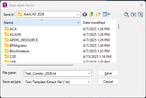
Command:
🧰 Load the LISP file with APPLOAD or by using (load "LayerList.lsp").
🚀 Run LLFP to open a save-file dialog and export the current drawing layer list to a .txt report.
📌 Main command function: c:llfp.
🧠 Main reporting helper: ax:layer-list.
📤 File writer helper: layer-list-fprint.
🎯 Target platform: AutoCAD and Civil 3D with Visual LISP COM support through vl-load-com, vlax-get-acad-object, and the AutoCAD ActiveX layer collection.
Description:
📘 LayerList scans the Layers collection of the active AutoCAD drawing and builds a sorted layer report that can be opened in a text editor or imported into Excel for CAD standards checking.
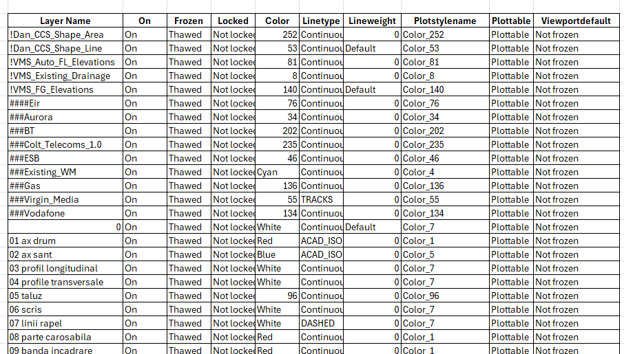
The user runs LLFP, chooses an output file path with getfiled, and the program writes a layer table using the current drawing name as the default report filename. The exported report includes practical AutoCAD layer management data such as layer name, visibility, freeze state, locked state, color, linetype, lineweight, plot style, plottable status, and viewport default freeze setting.
This AutoLISP utility is useful for DWG cleanup, CAD coordination, Civil 3D project review, plotting diagnostics, layer standard audits, and quick layer documentation. It is a non-destructive reporting tool: it reads layer properties and creates an external text file, but it does not modify the drawing geometry or change layer settings.
Helper function: (if any)
- 🚀 Command entry point —
c:llfpstarts the export workflow, asks the user where to save the report, and confirms whether the layer list was created. - 🔍 Layer scanning engine —
ax:layer-listloops throughvla-get-Layersfrom the active document and collects each layer record. - 📊 Layer property extraction — The routine reads name, on/off, frozen/thawed, locked/not locked, color, linetype, lineweight, plot style, plottable status, and viewport default freeze state.
- 🎨 Color formatting — AutoCAD color indexes 1 to 7 are converted to readable names such as Red, Yellow, Green, Cyan, Blue, Magenta, and White; higher color indexes are written as numbers.
- 📐 Lineweight formatting — The code converts AutoCAD lineweight values to readable decimal values and writes
Defaultwhen the layer uses default lineweight. - 🧠 Sorted output — The layer list is sorted alphabetically using
vl-sortandstrcase, making the exported report easier to review. - 📤 Text file writer —
layer-list-fprintwrites the header row and layer records to the selected.txtfile. - 🔐 COM startup check — The code verifies Visual LISP COM availability and loads COM support when needed before accessing the AutoCAD ActiveX API.
Functionalities:
- 📊 Export active drawing layers — Creates a text report of all layers in the current AutoCAD or Civil 3D drawing.
- 🔍 Audit layer visibility — Reports whether each layer is On or Off for faster drawing diagnostics.
- 🧊 Review freeze states — Shows whether each layer is Frozen or Thawed, including viewport default freeze information.
- 🔒 Check locked layers — Identifies locked and unlocked layers for CAD management and editing control.
- 🎨 Document layer appearance — Exports color, linetype, lineweight, and plot style values for standards comparison.
- 🖨️ Verify plotting behavior — Reports whether layers are plottable or not plottable, helping solve plotting and publishing problems.
- 📤 Excel-friendly output — Writes a text file that can be imported into Excel for filtering, sorting, documentation, and QA review.
- 🧹 Non-destructive CAD audit — Reads drawing layer properties without changing entities, layer definitions, styles, blocks, xrefs, or Civil 3D objects.
Result:
✅ The final result is a compact AutoCAD and Civil 3D layer inventory report that helps CAD users audit DWG layer standards, review plotting configuration, diagnose frozen or locked layers, and document drawing layer properties with fewer manual steps.
By exporting the layer table to a reusable text file, LayerList improves CAD quality control, supports Excel-based reporting, speeds up project documentation, and helps maintain cleaner AutoCAD and Civil 3D production drawings.
Images, animations etc.
XAML code:
<ResourceDictionary
 xmlns="http://schemas.microsoft.com/winfx/2006/xaml/presentation"
 xmlns:x="http://schemas.microsoft.com/winfx/2006/xaml"
 xmlns:src="clr-namespace:Autodesk.Windows;assembly=AdWindows">

 <src:RibbonToolTip x:Key="LayerList">
 <src:RibbonToolTip.ExpandedContent>
 <StackPanel>
 <TextBlock Background="AntiqueWhite" TextAlignment="Left">
<Bold>Function Syntax: LLFP</Bold>
<LineBreak/>
<Bold>Version: 1.1 Date: 20.06.2026 6:38:54PM</Bold>
<LineBreak/>
<Hyperlink>https://jtbworld.com/autocad-layer-list-lsp</Hyperlink>
<LineBreak/>
short_description: |<LineBreak/>
<Bold><Run Foreground="DodgerBlue">SEO Description</Run></Bold><LineBreak/>
<Run Foreground="White">🚀 LayerList is an AutoCAD and Civil 3D AutoLISP layer reporting utility for exporting the active drawing layer table.</Run><LineBreak/>
<Run Foreground="LimeGreen">It helps CAD users create Excel-friendly layer audits for visibility, freeze, lock, color, linetype, lineweight, plot style, and plottable status.</Run><LineBreak/>
<LineBreak/>
command: |<LineBreak/>
<Bold><Run Foreground="DodgerBlue">Main Command and Loading Method</Run></Bold><LineBreak/>
<Run Foreground="White">🧰 Load the file with </Run><Bold><Run Foreground="Orange">APPLOAD</Run></Bold><Run Foreground="White"> or </Run><Bold><Run Foreground="Orange">(load "LayerList.lsp")</Run></Bold><Run Foreground="White">.</Run><LineBreak/>
<Run Foreground="White">Run </Run><Bold><Run Foreground="Orange">LLFP</Run></Bold><Run Foreground="White"> to save the layer list to a text file.</Run><LineBreak/>
<Run Foreground="White">Main command function: </Run><Bold><Run Foreground="Orange">c:llfp</Run></Bold><Run Foreground="White">.</Run><LineBreak/>
<Run Foreground="White">Main helper functions: </Run><Bold><Run Foreground="Orange">ax:layer-list</Run></Bold><Run Foreground="White"> and </Run><Bold><Run Foreground="Orange">layer-list-fprint</Run></Bold><Run Foreground="White">.</Run><LineBreak/>
<LineBreak/>
description: |<LineBreak/>
<Bold><Run Foreground="DodgerBlue">Detailed Description</Run></Bold><LineBreak/>
<Run Foreground="White">📘 The program scans the AutoCAD ActiveX layer collection of the current drawing and builds a sorted layer report.</Run><LineBreak/>
<Run Foreground="White">The user runs </Run><Bold><Run Foreground="Orange">LLFP</Run></Bold><Run Foreground="White">, chooses an output path, and receives a text file containing the layer table.</Run><LineBreak/>
<Run Foreground="White">The exported data includes layer name, on or off state, frozen or thawed state, lock state, color, linetype, lineweight, plot style, plottable status, and viewport default freeze setting.</Run><LineBreak/>
<Run Foreground="LimeGreen">This is useful for DWG cleanup, AutoCAD layer standards, Civil 3D project review, plotting diagnostics, and Excel-based CAD quality control.</Run><LineBreak/>
<Bold><Run Foreground="DarkRed">Important:</Run></Bold><Run Foreground="White"> The routine is non-destructive and does not change the drawing.</Run><LineBreak/>
<LineBreak/>
helper_function: |<LineBreak/>
<Bold><Run Foreground="LimeGreen">Helper Logic</Run></Bold><LineBreak/>
<Run Foreground="White">🚀 </Run><Bold><Run Foreground="LimeGreen">Command entry point</Run></Bold><Run Foreground="White"> - c:llfp starts the export workflow, asks the user where to save the report, and confirms whether the layer list was created.</Run><LineBreak/>
<Run Foreground="White">🔍 </Run><Bold><Run Foreground="LimeGreen">Layer scanning engine</Run></Bold><Run Foreground="White"> - ax:layer-list loops through vla-get-Layers from the active document and collects each layer record.</Run><LineBreak/>
<Run Foreground="White">📊 </Run><Bold><Run Foreground="LimeGreen">Layer property extraction</Run></Bold><Run Foreground="White"> - The routine reads name, on/off, frozen/thawed, locked/not locked, color, linetype, lineweight, plot style, plottable status, and viewport default freeze state.</Run><LineBreak/>
<Run Foreground="White">🎨 </Run><Bold><Run Foreground="LimeGreen">Color formatting</Run></Bold><Run Foreground="White"> - AutoCAD color indexes 1 to 7 are converted to readable names such as Red, Yellow, Green, Cyan, Blue, Magenta, and White; higher color indexes are written as numbers.</Run><LineBreak/>
<Run Foreground="White">📐 </Run><Bold><Run Foreground="LimeGreen">Lineweight formatting</Run></Bold><Run Foreground="White"> - The code converts AutoCAD lineweight values to readable decimal values and writes Default when the layer uses default lineweight.</Run><LineBreak/>
<Run Foreground="White">🧠 </Run><Bold><Run Foreground="LimeGreen">Sorted output</Run></Bold><Run Foreground="White"> - The layer list is sorted alphabetically using vl-sort and strcase, making the exported report easier to review.</Run><LineBreak/>
<Run Foreground="White">📤 </Run><Bold><Run Foreground="LimeGreen">Text file writer</Run></Bold><Run Foreground="White"> - layer-list-fprint writes the header row and layer records to the selected .txt file.</Run><LineBreak/>
<Run Foreground="White">🔐 </Run><Bold><Run Foreground="LimeGreen">COM startup check</Run></Bold><Run Foreground="White"> - The code verifies Visual LISP COM availability and loads COM support when needed before accessing the AutoCAD ActiveX API.</Run><LineBreak/>
<LineBreak/>
functionalities: |<LineBreak/>
<Bold><Run Foreground="LimeGreen">Functionalities</Run></Bold><LineBreak/>
<Run Foreground="White">📊 </Run><Bold><Run Foreground="LimeGreen">Export active drawing layers</Run></Bold><Run Foreground="White"> - Creates a text report of all layers in the current AutoCAD or Civil 3D drawing.</Run><LineBreak/>
<Run Foreground="White">🔍 </Run><Bold><Run Foreground="LimeGreen">Audit layer visibility</Run></Bold><Run Foreground="White"> - Reports whether each layer is On or Off for faster drawing diagnostics.</Run><LineBreak/>
<Run Foreground="White">🧊 </Run><Bold><Run Foreground="LimeGreen">Review freeze states</Run></Bold><Run Foreground="White"> - Shows whether each layer is Frozen or Thawed, including viewport default freeze information.</Run><LineBreak/>
<Run Foreground="White">🔒 </Run><Bold><Run Foreground="LimeGreen">Check locked layers</Run></Bold><Run Foreground="White"> - Identifies locked and unlocked layers for CAD management and editing control.</Run><LineBreak/>
<Run Foreground="White">🎨 </Run><Bold><Run Foreground="LimeGreen">Document layer appearance</Run></Bold><Run Foreground="White"> - Exports color, linetype, lineweight, and plot style values for standards comparison.</Run><LineBreak/>
<Run Foreground="White">🖨️ </Run><Bold><Run Foreground="LimeGreen">Verify plotting behavior</Run></Bold><Run Foreground="White"> - Reports whether layers are plottable or not plottable, helping solve plotting and publishing problems.</Run><LineBreak/>
<Run Foreground="White">📤 </Run><Bold><Run Foreground="LimeGreen">Excel-friendly output</Run></Bold><Run Foreground="White"> - Writes a text file that can be imported into Excel for filtering, sorting, documentation, and QA review.</Run><LineBreak/>
<Run Foreground="White">🧹 </Run><Bold><Run Foreground="LimeGreen">Non-destructive CAD audit</Run></Bold><Run Foreground="White"> - Reads drawing layer properties without changing entities, layer definitions, styles, blocks, xrefs, or Civil 3D objects.</Run><LineBreak/>
<LineBreak/>
result: |<LineBreak/>
<Bold><Run Foreground="DodgerBlue">Final Result</Run></Bold><LineBreak/>
<Run Foreground="White">✅ The final result is a compact AutoCAD and Civil 3D layer inventory report for CAD auditing, plotting review, and drawing documentation.</Run><LineBreak/>
<Run Foreground="LimeGreen">It reduces manual layer checking, improves DWG quality control, and supports cleaner production drawings.</Run><LineBreak/>
<LineBreak/>
additional_info: |<LineBreak/>
<Bold><Run Foreground="DarkRed">Important Notes</Run></Bold><LineBreak/>
<Run Foreground="White">🔴 LayerList is a reporting tool only. It does not rename, delete, freeze, thaw, lock, unlock, or modify layers.</Run><LineBreak/>
<Run Foreground="White">📌 The output is a plain text table that can be imported into Excel, not a strict comma-separated CSV file.</Run><LineBreak/>
<Run Foreground="White">🧩 The code does not edit Civil 3D ProfileView, SectionView, Alignment, labels, bands, surfaces, corridors, or styles.</Run><LineBreak/>
<Run Foreground="White">🔐 The report reflects the active drawing layer table at the time the command is executed.</Run><LineBreak/>

</TextBlock>

 <!-- Use MediaElement for GIF (static first frame) and Image as fallback -->

</StackPanel>
 </src:RibbonToolTip.ExpandedContent>
 </src:RibbonToolTip>
</ResourceDictionary>
Leave a Reply
You must be logged in to post a comment.