
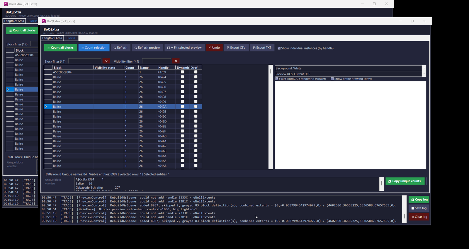
BoQExtra
- 🚀 Modeless AutoCAD interface – opens with
BoQExtraand stays available while the user works in the drawing. - 📐 Length and area measurement – calculates geometry quantities from selected AutoCAD and Civil 3D model-space objects.
- 🔢 Per-object quantity table – displays handle, layer, object type, length, area, closed status, minimum length, maximum length, and repeated vertical dimensions.
- 🧠 Formula profiles – applies saved BoQ formulas, decimal formatting, Excel-ready expressions, CEILING rounding, and automatic Profile_002 layer divisors.
- 📝 Field-based MTEXT placement – places raw, length, area, length plus area, detailed, CEILING, or profile-based results into AutoCAD as MTEXT.
- 📋 Clipboard output – copies formulas, raw values, selected table data, block counts, unique counters, and logs for quick reuse in Excel or project documentation.
- 🧩 Dynamic block counting – counts block references by effective name, visibility state, dynamic status, xref status, and individual handle.
- 🔢 Bottom unique block counter – shows each unique block name and its total number of visible instances in the current filtered block table.
- 🏷️ Dynamic visibility editing – changes selected dynamic block visibility states directly from the Blocks tab.
- 🎨 Layer management – changes the layer of selected geometry or selected block references using wildcard-filtered layer lists.
- 🧹 Delete and undo tools – deletes selected entities or block references and provides undo access in both main tabs.
- 🟧 Polyline cleanup actions – closes selected polylines, joins selected polylines, and closes two selected parallel polyline rows without centerline creation.
- 🔍 Model-space selection synchronization – selecting multiple rows in the grid can also select the corresponding objects in AutoCAD model space.
- 📌 Model-space zoom control – zooms to the current row, selected rows, or selected model-space objects for visual checking.
- 🎨 Preview with drawing context – shows selected geometry in highlight color and unselected context geometry in gray, with UCS rotation, zoom, pan, fit selected, and fit all.
- 📤 CSV and TXT export – exports Length and Area tables, Blocks tables, unique block counters, and logs for downstream reporting and QA workflows.
- 🔒 Diagnostic logging – records startup checks, build information, active drawing path, Civil 3D assembly detection, action history, warnings, and errors.
- 🚀 Modeless AutoCAD interface – opens with
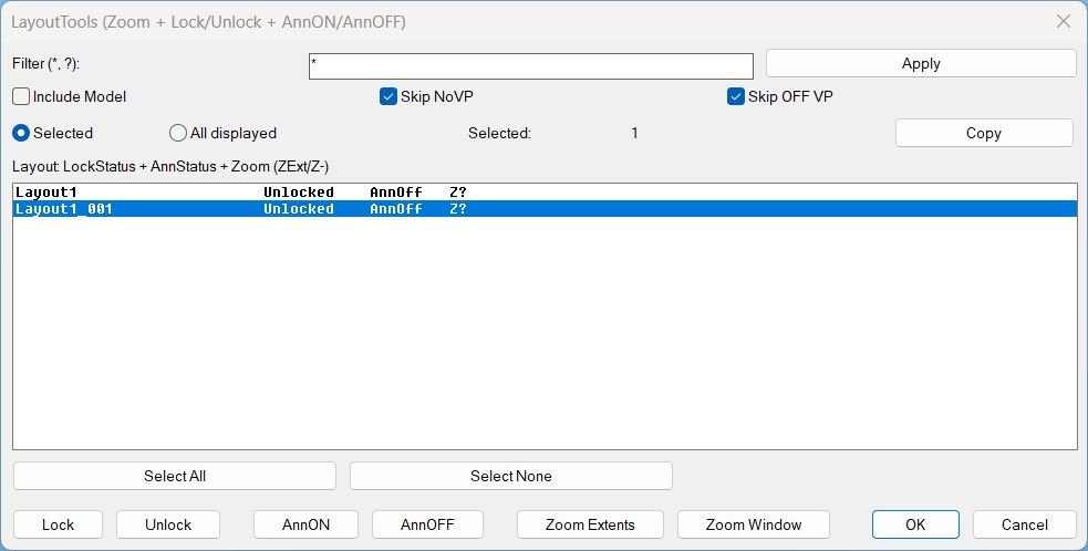
LayoutTools
Functionalities- Layout list and selection
- Filter layouts by pattern and refresh the list using Apply.
- Toggle Include Model to show or hide Model from the list, while actions still avoid Model for viewport operations.
- Choose targeting scope between Selected and All displayed layouts.
- Use Select All and Select None to manage multi selection quickly.
- Display per layout columns for lock state, annotation state, and zoom status.
- Viewport locking
- Lock locks paper space viewports across the target layouts using DisplayLocked.
- Unlock unlocks paper space viewports across the target layouts.
- Skip NoVP prevents actions on layouts that have no usable paper space viewports.
- Skip OFF VP ignores viewports that are turned off when applying lock changes.
- Lock status is shown as Locked, Unlocked, Mixed, NoVP, or Model.
- Annotation visibility
- AnnON sets ANNOALLVISIBLE to 1 for the target layouts.
- AnnOFF sets ANNOALLVISIBLE to 0 for the target layouts.
- Annotation state is displayed as AnnOn, AnnOff, or Ann? if it cannot be read.
- Paper space zoom
- Zoom Extents applies a paper space zoom extents in each target layout and records the status as ZExt.
- Zoom Window prompts the user for two corners, applies the same window to each target layout, and records the status as Z-.
- Zoom status is shown as ZExt, Z-, or Z? when unknown, and is persisted in the DWG.
- Clipboard reporting
- Copy exports a tab separated report of layout name, lock status, annotation status, and zoom status for the current target scope.
- Operational safeguards
- Actions are wrapped in a single undo mark per batch operation for easier rollback.
- The tool restores TILEMODE, CTAB, and MSPACE after operations that switch tabs or paper space state.
- Layout list and selection
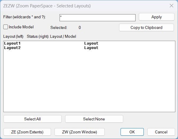
Zoom Extend Window
Functionalities- Dialog UI with filter, multi-select list, select all, select none, and selected count display.
- Layout filtering using wildcards to quickly isolate target layout tabs.
- Clipboard export of selected layout names and their status, formatted line-by-line for paste into other tools.
- Zoom Extents across selected layouts in Paper Space with stable post-dialog execution.
- Zoom Window across selected layouts using one picked window applied consistently to all layouts.
- Paper Space enforcement by forcing MSpace false before zooming to avoid viewport context issues.
- Undo grouping using StartUndoMark and EndUndoMark for clean rollback of multi-layout operations.
- Robust fallbacks for zoom (COM first, then command-based) and for clipboard copy (multiple methods).
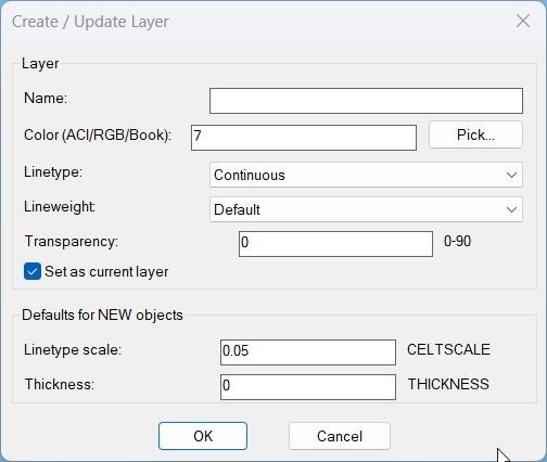
LayerCreation
- • Dual interface — LayerCreation uses DCL when available; otherwise it runs NEWLAYERCLI which prompts in the command line and always works.
- • Layer name validation — rejects empty names and names containing forbidden characters (\ / : ; * ? " < > | , =).
- • Color selection — supports three color modes: ACI index (62), RGB truecolor (420), and Color Book color (430), with persistent “last used” values.
- • Manual color input — dialog allows typing ACI, r,g,b, or BOOK$COLOR; parser converts it into the internal selector list used for TrueColor application.
- • Linetype management — linetypes are listed from the drawing; missing linetypes can be auto-loaded before assignment.
- • Layer creation/update — if the layer does not exist, creates it; then sets Linetype, Lineweight, and Transparency using -LAYER scripted calls; color is applied afterwards via TrueColor API to support RGB/books.
- • Defaults for new objects — applies CELTSCALE (default 0.05), CETRANSPARENCY (default 0), and THICKNESS (default 0) using a safe setvar wrapper so invalid settings do not cancel the command.
- • Set current toggle — both UI flows allow setting the created/updated layer as current (default Yes/checked).
- • Cleanup — DCL version writes a unique temp dialog file, loads/unloads it, then deletes it; color selection is persisted for the next run.
CopySelection_vs.01
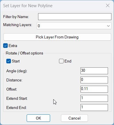
• Segment duplication: Quickly duplicates only a chosen portion of an LWPOLYLINE between two points, instead of copying and trimming manually. • Layer targeting: Lets you send the new polyline and its copies directly onto a specific layer chosen from a filtered list or from a picked object, keeping layer structure organized. • Optional advanced transforms: When Extra is on, you can extend ends, rotate the new polyline around the start or end point, shift it perpendicular to its own direction, and generate several parallel copies at fixed offset distances. • Preset offset library: Built in presets (DN110, KK I to KK IV) automatically set offset distances that match typical pipe or trench sizes, saving you from repeatedly typing standard values. • Interactive Apply and Undo: You can iteratively test different settings: Apply to create geometry, Undo to remove the last created batch, adjust dialog values, and repeat, all on the same source polyline selection. • Robust cancellation: If you close the dialog or choose Cancel after one or more Apply actions, the routine automatically undoes all those actions so the drawing returns to its original state. • Single step final undo: When you finish with OK, all geometry created in this session remains, but the entire operation is enclosed in an UNDO group so one undo command removes everything if needed.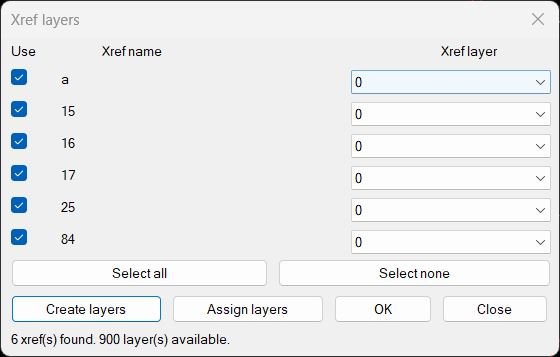
CreatesXrefsLayersAssign_vs.00
Functionalities: • Automatic xref detection: every external reference in the drawing is listed in the dialog. • Per xref enable checkbox: only checked xrefs will be processed by create or assign actions. • Per xref layer popup: each xref can be assigned to any existing layer through a dropdown. • Create layers button: makes layers named _xref_xrefName for all checked xrefs, ensures they exist, refreshes the popups, and selects the new layer for those rows. • Assign layers button: moves all inserts of the checked xrefs to the currently selected layer, in both model space and paper space. • Select all and Select none: quick buttons to toggle all checkboxes in one click. • Dynamic layer list: if new layers are created the dialog reloads the layer list so the new layers can be picked immediately. • OK button: performs the assign action then closes the dialog. • Close button: exits without changes.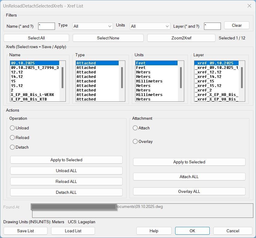
UnReloadDetachSelectedXrefs_00
Functionalities:- Filter by Name: Wildcard filter using
*and?patterns. - Filter by Type: Dropdown list populated from Xref types present in the drawing (All / Attached / Overlay).
- Filter by Units: Dropdown list populated from units present in the drawing (All / mm / m / ft / …).
- Filter by Layer: Wildcard filter using
*and?patterns. - Selection control: Select All / Select None, selection counter, and multi-select list behavior used as “checkboxes.”
- Save List: Writes header HOSTINSUNITS and HOSTUCSNAME, then per selected xref writes Name|Type|FoundAt|UnitsCode|Layer.
- Load List (per xref): UCS reset to World → set drawing INSUNITS to the xref UnitsCode → attach if missing (Found At + Type) → reload → force inserts to saved Layer.
- Load List (final restore): Restores original drawing INSUNITS and UCS; keeps named UCS if present, otherwise uses a temporary UCS name for safe restore.
- Apply to Selected (Operation): Unload / Reload / Detach on selected xrefs only.
- Apply to Selected (Attachment): Attach / Overlay type conversion on selected xrefs only.
- ALL operations: Unload ALL / Reload ALL / Detach ALL / Attach ALL / Overlay ALL for all xrefs, executed with UCS+view preservation to prevent user context changes.
- Zoom2Xref: Zooms to the selected xref extents without requiring manual selection in the External References palette.
- Filter by Name: Wildcard filter using
Multiple_text_mtext_2
• Multi text merge: Merges multiple individual TEXT and MTEXT items into a single MTEXT object for easier global editing. • Paragraph preservation: Keeps each original TEXT line as its own paragraph inside MTEXT so line structure is not lost. • Underline aware: Translates “%%U” underline codes into proper MTEXT underline formatting that works in modern text styles. • Style consistency: Uses the first selected text object as a template for layer, color, text style, and height, ensuring the new MTEXT matches the existing annotation style. • Alignment and rotation: Attempts to reproduce the same alignment and rotation of the first entity so the new MTEXT appears in the same visual position and orientation. • Space aware: Automatically works in model space or paper space depending on the current active space of the document. • Automatic cleanup: Removes all original text entities after creation of the MTEXT, preventing duplicates on screen.Copy_to_Clipboard_Xref
• Nested Entity Picking: Supports selecting items inside block references with full transformation accuracy. • Supported Types: TEXT, MTEXT, DIMENSION (with override or measurement), LEADER (via Annotation), and BLOCK attribute text. • Temporary Copy System: Creates duplicates on the current layer for consistent extraction. • Text Aggregation: Multiple selected entities produce a combined clipboard output, each separated by line breaks. • Clipboard Automation: Automatically exports collected text into Windows clipboard without extra interaction. • Cleanup Guarantee: All temporary entities are removed after copying, leaving the drawing unmodified.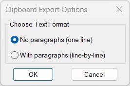
Copy_to_Clipboard
• Two Export Modes: Choose between flat single-line text or structured line-by-line paragraphs. • MTEXT Formatting Removal: Eliminates all inline codes such as A1;, H0.7;, fArial;, L, O, etc. • Unicode Handling: Converts U+XXXX hexadecimal escape sequences into real characters (≥ ≤ ± °). • Paragraph Logic: Cleans unwanted “P” markers while preserving valid words like “PE-HD”. • Clipboard Automation: Sends the processed result directly to the Windows clipboard without prompting. • Wide Object Support: Works with TEXT, MTEXT, DIMENSION, MULTILEADER, attributes, and attribute blocks. • Error Safety: Custom *error* handler ensures clipboard object is released even during failures.RotateMtextVport
Functionalities:- Calculates current viewport rotation by measuring UCS X-axis angle in WCS
- Prompts user to select TEXT and/or MTEXT objects
- Iterates through selected objects and applies rotation based on object type
- For MTEXT: sets rotation to 0° and attachment point to top-left
- For TEXT: sets rotation to viewport angle and alignment to left
- Displays message if no objects are selected
Lower
• Supports TEXT & MTEXT: Works on both object types simultaneously. • Uppercase Mode: Converts all selected text content to uppercase. • Lowercase Mode: Converts all selected text content to lowercase. • Default Behavior: Uppercase is automatically used if no choice is provided. • Non-Destructive: Only the string content is modified; all other entity properties remain unchanged. • Environment-Safe: Resets all system variables changed during execution.Upper
• Select all TEXT + MTEXT automatically using (ssget). • Loops through each entity and converts its content to uppercase. • Uses STRCASE to ensure consistent uppercase transformation. • Displays “Done.” when complete.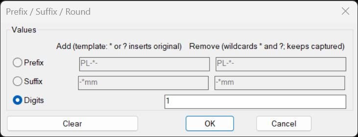
PrefixSuffixRound
• Prefix add/remove — Add or strip prefixes to/from text, with either literal strings or wildcard patterns that can embed or preserve parts of the original text • Suffix add/remove — Add or strip suffixes similarly, with anchored wildcard matching at the end of the string • Wildcard templates — Patterns can use “*” and “?” such that the original text is reinserted into a new structured form (e.g., “PRE_*_SUF”, “?OLD?”) • Safe numeric rounding — Numeric-only texts are converted to rounded values with a given number of decimal digits, while non-numeric text is left unchanged • Per-entity text source — For INSERT, only the first attribute’s text is modified; for TEXT/MTEXT/ATTRIB, the DXF 1 text string is directly edited • Dialog radio logic — Uses USERR1 system variable and radio buttons to switch between Prefix, Suffix, and Digits modes, enabling/disabling relevant input fields dynamically • Persistent UI state — Stores the last active mode and input values (prefix/suffix add/remove strings and rounding digits) so they appear pre-filled next time • One-shot and quick commands — You can run the full dialog via PREF_SUFF_OKR_TXT or quickly reapply the last stored prefix, suffix, or rounding via PREF, SUFF, OKR_TXTPlusMinusNumericValue
• Dialog-driven numeric change — User sets plus/minus value and which numeric position(s) to affect before any entity is touched • Integer and real support — Detects whether the input increment contains a decimal point and handles values as REAL when needed, preserving or extending decimal places • Location modes — Supports changing a specific numeric block by index, all numeric blocks at once, or using interactive List mode to review positions before deciding • MTEXT-aware parsing — Respects MTEXT control sequences (like C, H, etc.), treating them as units so formatting is preserved around changed numbers • Attribute mode choice — For ATTDEF objects, prompts once whether to modify Tag or Text, then applies this choice to all attribute definitions in the selection • Per-entity processing — Reads each entity’s current string, runs parseString and adjustString, and writes back the new string using the proper VLA setter (TagString or TextString) • Undo-safe update — Starts an UNDO mark before making changes and ends it afterwards, so the user can revert the entire batch in a single undo operation • Persistent defaults — Saves the last used numeric increment and location string to the registry and global variables, so the dialog auto-fills them next time • Negative number support — Optional global flag GlbVarInvAllowNeg allows proper recognition and editing of signed numbers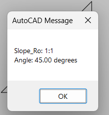
Slope_Ro
• Two-point slope measurement — Uses user input for start and end points • Imperial 12-run standard — Converts slope to a rise-per-12-units format • Automatic ratio simplification — Ensures output is reduced (e.g., 12:6 → 2:1) • Angle reporting — Provides the slope angle with two decimal precision • Error-safe logic — Prevents zero-division and handles flat slopes correctly • Clean environment — Restores system variables on exitRegion2Polyline
• Automatic REGION selection No need to pick objects — all REGIONs are processed automatically • Topology reconstruction Correctly orders exploded segments into a clean closed loop • Arc bulge preservation Converts arcs into bulges for accurate curve representation in LWPOLYLINE format • Normal and elevation restoration Preserves the REGION’s original 3D plane orientation • Deletion of intermediate entities Exploded parts and original REGION are removed to keep drawing tidy • Undo support Protected by an undo mark for safe rollback of the entire conversion • Robust endpoint matching Ensures proper polyline closure even when geometry contains reversed or unordered segments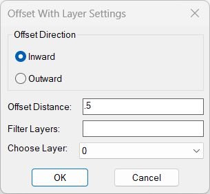
OffsetAndLayer
• Dialog-driven offset — Combines direction, distance, and layer control in one interface • Distance parsing — Converts the distance input from text to a numeric value using distof • Layer filtering — Allows narrowing down layer selection using wildcard text input • Planarity check — Only offsets 2D planar entities and skips 3D polylines or non-planar objects • Area-based direction check — Determines if offset is Inward or Outward by comparing the new area with the original • Automatic direction correction — Deletes and recreates the offset if wrong direction was applied • Layer assignment — Puts every created offset curve onto the selected layer • Failure counting — Tracks objects too small to offset inward and reports the number • Undo-safe execution — Encloses all operations within a single undo group • Temporary file handling — Deletes the temporary DCL file after the dialog closesMiddleLinePolylines_2
• Automatic curve type handling Uses the generic curve API so the same logic works across lines, polylines, arcs, splines, and ellipses • First and last driven logic Only the first and the last objects in the selection are used, which allows flexible window or crossing selection while still defining two sides • Closed curve safeguard Skips processing when a selected curve has identical start and end points, avoiding problematic closed input • Midpoint centerline Calculates midpoints between the two start points and between the two end points then draws the centerline through these midpoints • Planar output Uses only X and Y from the picked curves and ignores Z so the resulting LWPOLYLINE is a clean two dimensional object • Silent behaviour No command line prompts are issued; if the conditions are not met, nothing is created and the routine exits quietly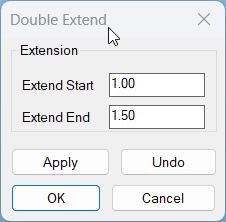
Lengthen
• Separate start and end control: Lets you extend the start and end of each entity by different distances so you can lengthen segments asymmetrically where needed. • Multi type support: Handles plain lines, circular arcs, lightweight polylines and old style polylines, preserving bulges and widths where appropriate. • Arc safety: For arcs and bulged segments the extension length is limited so that the implied arc never wraps around into a full circle, preventing invalid geometry. • Iterative preview: Apply can be pressed repeatedly with different extension values in one session, allowing you to visually tune the result while Undo steps back to the previous version each time. • Global persistence: The extension values are stored in global variables so the next time you run the command the dialog opens with the last used start and end distances already filled in. • Undo group integration: All modifications performed while the command is active are wrapped inside a single AutoCAD UNDO group, making it easy to revert the entire operation with one undo if needed. • Selection reuse: The initial selection set is kept for the whole dialog loop, so you do not need to re select objects between Apply and Undo cycles.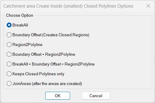
InteriorPolylinesArea
• Unified workflow One command controls multiple area-processing operations • Intersection breaking Prepares geometry for clean area creation • Inside boundary generation Using region + offset-edge logic from robust Lee Mac tools • Region → Polyline Converts regions into accurate closed polylines with proper bulges • Pipeline commands rb04 and rb05 execute chained multi-step workflows automatically • Cleaning tool Deletes all open polylines inside a window selection • Area joining Regions are boolean-united then converted back to closed polylines with maintained properties • Undo safety Uses undo marks and restores system variables after operations • Temporary file cleanup Removes DCL file after use and deletes interim geometry during processingCopySelection
• Polyline validation Ensures the selected object is a LWPOLYLINE • Point projection Snaps the picked points to the closest polyline points before using them • Distinct point enforcement Rejects overlapping points and forces user to choose a valid second point • Parameter order correction Swaps start and end parameters when reversed by selection • Layer dialog with memory Recalls last filter and layer using stored environment variables • Layer filtering Dynamically filters layer names using wildcard matching • Pick layer from drawing Lets the user click any object to inherit its layer • Segment extraction Reconstructs only the portion between the two parametric points including widths and bulges • New polyline creation Builds a fresh LWPolyline with original properties but on the new layer • Cleanup Removes temporary DCL file after dialog closes • Cancellation handling Stops with a message if no valid layer is chosen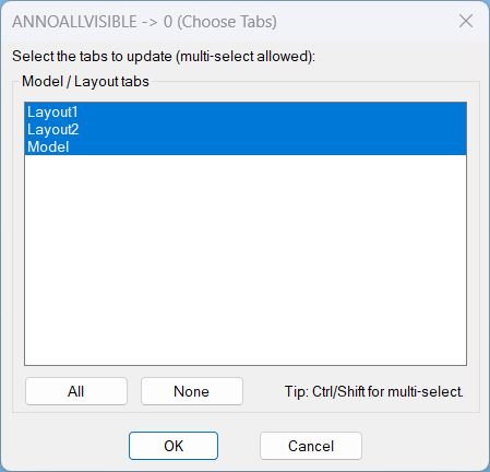
AnnoAllOff
- • Runtime DCL generation creates a dialog file in a temp location and loads it for the session.
- • Multi-select tab picker allows choosing any combination of Model and Layout tabs for updating.
- • All button selects every tab in the list box using a generated index string.
- • None button clears the selection to prevent changes from being applied.
- • Per-tab update switches CTAB for each chosen tab and sets ANNOALLVISIBLE to 0.
- • Layout handling forces paperspace on layout tabs by setting MSPACE false when TILEMODE indicates a layout context.
- • State restoration restores prior CTAB, TILEMODE, and MSPACE values after processing.
SelectLayout
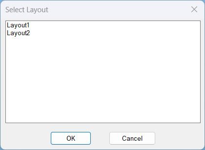
Functionalities:- Accesses all layouts in the active drawing document
- Filters out Model space, collecting only paper space layout names
- Dynamically creates a DCL file with list box interface specifications
- Writes dialog definition including dimensions and interaction settings
- Loads and displays the custom dialog box
- Populates list box with all available layout names
- Captures user selection from list box
- Switches to selected layout using AutoCAD LAYOUT command
- Cleans up temporary files after use
- Displays confirmation message with selected layout name
GoToLayout
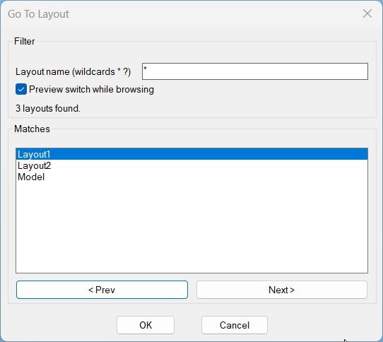
- Wildcard filter input supporting * and ? to quickly narrow layout names.
- Case-insensitive matching and sorting for reliable results regardless of layout name casing.
- Preview toggle that can switch CTAB live as the user browses matches.
- Navigation buttons < Prev and Next > with wrap-around to cycle through matches efficiently.
- Automatic enabling and disabling of OK and navigation when zero layouts match the filter pattern.
- Remembers the last used pattern in a global variable so subsequent runs start with the previous filter.
- Restores the original tab on cancel or dialog close for safe browsing workflows.
AnnoAllOn
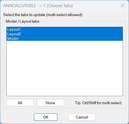
- Runtime DCL generation creates and loads a temporary dialog file for tab selection.
- Multi-select tab picker supports choosing any combination of Model and Layout tabs to update.
- All selects every listed tab by setting the list box to an auto-generated index string.
- None clears the list box selection to prevent changes from being applied.
- Per-tab application switches CTAB to each selected tab and applies ANNOALLVISIBLE value 1.
- Layout handling forces paperspace on layout tabs by setting MSPACE to false when in a layout context.
- State restoration restores prior CTAB, TILEMODE, and MSPACE after processing completes.

Copy2Layouts
- • Runtime DCL generation writes and loads a temp dialog with a unique name on each run.
- • Pick from drawing captures a selection set once and displays only Total: N in the dialog.
- • Layout filtering supports wildcard patterns * and ? and applies case-insensitive matching.
- • Multi-select target layouts copies to any subset of filtered layouts, with Select All and Select None for fast control.
- • Copy enable/disable disables the Copy button when no objects are selected to reduce invalid runs.
- • ActiveX CopyObjects copies converted VLA objects into each destination layout’s paper-space block to avoid command-based copy/paste issues.
- • UNDO grouping wraps the copy operation in UNDO Begin/End so the entire multi-layout copy can be undone in a single step.
- • Looped dialog workflow Apply Filter and Pick reopen the dialog, while a successful Copy ends the command.
SetUpUnits
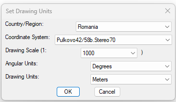
[‘🌍 Opens a country and region based Civil 3D drawing setup dialog.’, ‘🗺️ Lists coordinate system codes for the selected country, region, UTM group, or world coordinate system category.’, ‘🚩 Shows a live flag preview in the DCL dialog using external flag pixel data.’, ‘📐 Lets the user select drawing scale values such as 1, 20, 50, 100, 200, 500, 1000, 2000, and 5000.’, ‘📏 Lets the user choose drawing units including feet, meters, millimeters, centimeters, decimeters, and inches.’, ‘🧭 Lets the user choose angular units including degrees, radians, and grads.’, ‘🔧 Applies the chosen Civil 3D coordinate system code to the active drawing.’, ‘⚙️ Applies drawing scale, angular unit mode, and drawing unit mode through Civil 3D COM settings.’, ‘🇷🇴 Starts with Romania, scale 1000, degrees, and meters as the default dialog selections in the uploaded code.’, ‘🧰 Generates the DCL dialog at runtime in the AutoCAD temporary folder and deletes it after use.’, ‘🎨 Converts RGB flag data to AutoCAD ACI colors for DCL image rendering.’, ‘⚡ Uses run-length encoding logic so consecutive same-color pixels are drawn efficiently.’, ‘📌 Prints the applied coordinate system, scale, angular unit, and drawing unit result to the AutoCAD command line.’]
MultiOffsetBothSidesWithLayer
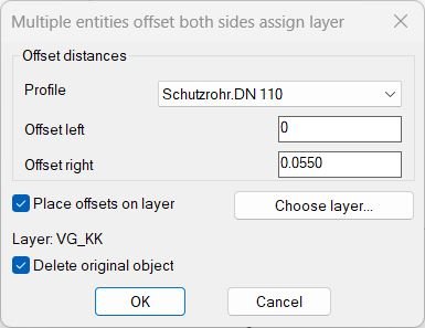
Main Functionalities: • Perform bi-directional offset (left and right) on multiple selected lines. • Apply predefined offset profiles or set custom offset distances. • Delete originals after offset creation (optional). • Change the entity layer to a selected target before offsetting (optional). • Maintain proper layer inheritance for new offset lines. • Use of ActiveX and(vl-load-com) to manage AutoCAD objects dynamically. • Temporary DCL files created with (vl-filename-mktemp) are auto-deleted after dialog use.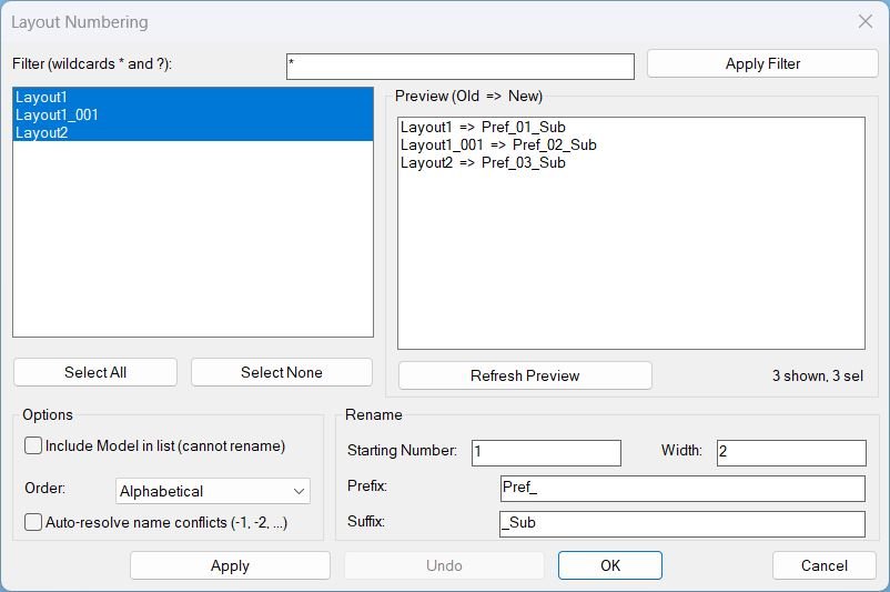
LayoutNum
- Wildcard filter with a dedicated Apply Filter action that rebuilds the displayed list without renaming anything.
- Multi-select layouts with Select All and Select None shortcuts and a live status indicator showing shown and selected counts.
- Preview panel showing proposed renames as Old => New, with a Refresh Preview button and auto-refresh on option changes.
- Renaming options including starting number, zero-padding width, prefix, suffix, order mode (tab order or alphabetical), and auto-resolve for conflicts by appending -1, -2, and so on.
- Non-destructive handling of Model when included: it can be listed but is blocked from renaming and triggers validation alerts if selected for rename.
- Bottom controls: Apply renames and keeps dialog open, Undo restores prior rename sets, OK renames and closes, Cancel closes without applying a new rename.
- Safety rule avoids calling AutoCAD UNDO from DCL callbacks and instead uses a manual undo stack, while still grouping changes with VLA undo marks.
- Persists last-used settings across runs for faster repeat usage.
LockAllVp
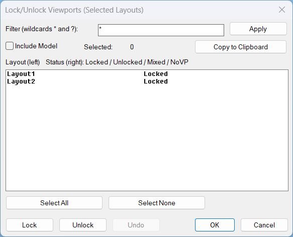
- • Filter layouts using wildcard patterns (*, ?) and click Apply to rebuild the displayed list.
- • Multi-select layouts from the list for batch processing.
- • Select All and Select None for fast selection control.
- • Lock all detected Paper Space viewports in the selected layouts.
- • Unlock all detected Paper Space viewports in the selected layouts.
- • Show per-layout current status (Locked / Unlocked / Mixed / NoVP) so the user can validate before and after changes.
- • Undo the last operation (and potentially multiple operations) using an internal restore stack, avoiding unstable undo calls inside the dialog.
- • Copy to Clipboard selected layout names and status for documentation or reporting.
- • Preserve user environment by restoring CTAB and minimizing command echo during processing.

Zoom Extend
Functionalities- Dialog UI for filtering and multi-selecting layouts.
- Select All and Select None selection tools and selected count display.
- Clipboard export of selected layout names and status.
- Zoom Extents in Paper Space across the selected layouts.
- Undo grouping for multi-layout operations using StartUndoMark and EndUndoMark.
- Robust fallbacks for temp DCL creation and zoom execution.
Zoom Window
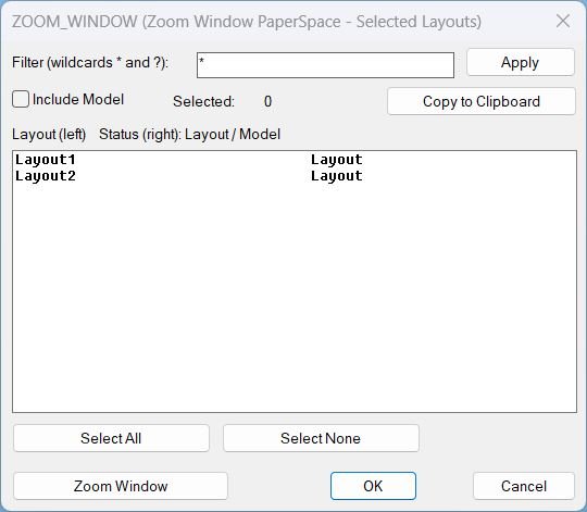
Functionalities- Dialog UI for filtering and multi-selecting layouts.
- Select All and Select None selection tools and selected count display.
- Clipboard export of selected layout names and status.
- Zoom Window in Paper Space across the selected layouts using one picked window applied consistently.
- Undo grouping for multi-layout operations using StartUndoMark and EndUndoMark.
- Robust fallbacks for temp DCL creation and zoom execution.
Layouts_list
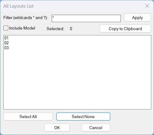
- Wildcard layout filtering with an explicit Apply button that rebuilds the displayed list only.
- Optional Include Model toggle controlling whether Model appears in the list.
- Multi-select list with live selected count and selection preservation when the filter changes.
- Select All and Select None for rapid selection management.
- Copy to Clipboard that outputs one layout name per line to the Windows clipboard, with multiple copy mechanisms for robustness.
- DCL is embedded in the LSP, written to a temp file with a unique dialog name per run, then removed on exit.
FreezeLayersInVP
- • Runtime DCL generation writes the dialog to a temp file each run, loads it, then deletes it after closing.
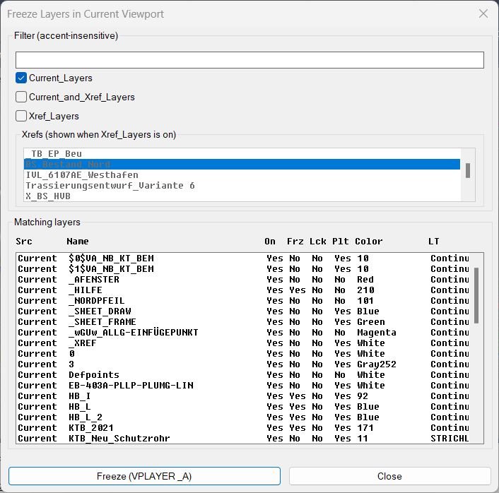
- • Sticky header shows the faux-column titles in a fixed-width text control above the layer list.
- • Faux columns display: Src, Name, On, Frz, Lck, Plt, Color, LT, Desc using fixed-width padding.
- • Accent-insensitive filtering normalizes both filter text and layer names before matching, improving usability with localized naming.
- • Scope toggles to include Current_Layers, Current_and_Xref_Layers, and Xref_Layers when filtering the layer list.
- • Xref picker becomes enabled only when Xref_Layers is on and can restrict results to layers belonging to selected Xrefs.
- • Persistent settings remembers last filter text, toggle states, and chosen Xrefs using environment variables for the next session.
- • Multi-select layer freeze freezes each selected layer using VPLAYER with the freeze option and the _A scope as implemented in the routine.
- • Note the routine freezes with VPLAYER _A as coded, and the comment indicates _C could be used to target only the current viewport if desired.
TitleBlocksTools
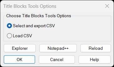
Functionalities:- Displays unified menu dialog with radio buttons for Export CSV or Load CSV operations
- Resolves LISP file path dynamically from USERPROFILE environment variable
- Main dialog includes Explorer, Notepad++, and Reload buttons for file management
- Help button launches comprehensive documentation dialog
- Export workflow (EXPTBCSV_EXPORT):
- Prompts user to pick titleblock inserts until ENTER pressed
- Collects unique block names from selections
- Scans all paper space layouts for matching inserts with attributes
- Displays numbered list of all unique attribute tags found
- Accepts “All”, “None”, or range input (1,3,5-7) for tag selection
- Prompts for CSV save location with drawing name as default
- Writes CSV with DWG, Layout, Block columns plus selected tags
- Applies Excel-safe formatting (single-quote prefix for dates/formulas)
- Escapes special characters (commas, quotes, newlines) per CSV standard
- Attempts to auto-open CSV in Excel via multiple detection methods
- Update workflow (UTB2):
- Prompts for CSV file if UTB2:csv not preset
- Validates CSV format and searches for current drawing name in first column
- Applies optional layout filter if UTB2:lay is true (CSV has Layout column)
- Applies optional block filter if UTB2:blk is true (CSV has Block column)
- Uses wildcard filter UTB2:ftr to limit scope to specific block names
- Resolves effective names for dynamic/anonymous blocks
- Iterates through all attributed inserts matching filters
- Updates only attributes with tags matching CSV headers
- Changes only when current value differs from CSV value
- Supports duplicate attribute tags by removing processed items from value list
- Creates single undo mark for entire batch operation
- Reports count of attributes and blocks updated
- Help dialog functionality:
- Displays LISP file path at top of help content
- Shows comprehensive documentation with bullet points and arrows
- Unicode toggle switches between Unicode symbols and ASCII alternatives
- Rebuilds and refreshes display when Unicode preference changes
- Copy Selected copies highlighted lines to clipboard
- Copy All copies entire help text to clipboard
- Copy Path copies LISP file location to clipboard
- Explorer button navigates to LISP folder with file selected
- Notepad++ button opens LISP in editor with fallback to Notepad
- File management features:
- Reload button executes (load) on current LISP file without closing AutoCAD
- Explorer integration uses /select argument for file highlighting
- Notepad++ detection tries configured path, cmd shell, and Notepad fallback
- Path copying via MSHTML clipboard object for reliability
- Persistent state management:
- *tbt-last-option* remembers last radio button selection
- *tbt-unicode* remembers Unicode/ASCII preference
- *NPP:Path* stores custom Notepad++ installation path
- CSV parsing handles alternative delimiters (semicolon) from regional settings
- Removes case sensitivity for drawing name matching
- Supports filenames with or without .dwg extension in CSV
- Handles CSV cells containing embedded commas, quotes, and line breaks
Zoom2Layer
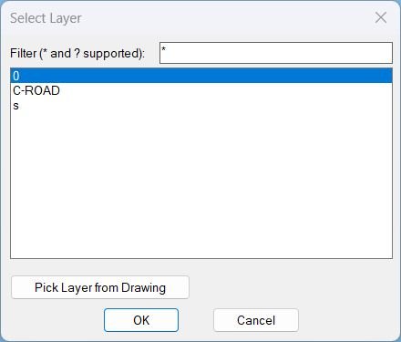
- • Layer filtering with wildcard patterns entered in the dialog filter box.
- • Layer list scope includes only layers that are not off and not frozen (visible/unfrozen set).
- • Pick Layer from Drawing button temporarily exits the dialog so the user can select an object and adopt that object’s layer as the new filter, then reopens the dialog.
- • Persisted filter stored in CHLAY-LAST-FILTER and restored on next run.
- • Zoom-to-layer extents by collecting all objects on the selected layer and computing min/max XY bounds from each entity’s bounding box.
- • Robustness uses guarded ActiveX calls and skips entities that do not support GetBoundingBox.
RenameLayer
- • Undo safety — starts an Undo mark at the beginning and ends it at completion so the full batch can be undone as one unit.
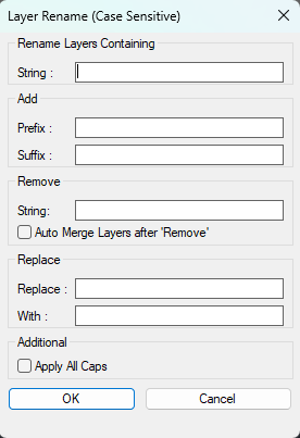
- • Dialog inputs — captures: Search substring, New Prefix, New Suffix, Remove substring, Replace-from (OSTR), Replace-to (NSTR), Apply All Caps toggle, and Auto Merge toggle.
- • Replace validation — enforces that Replace fields must be provided as a pair (both filled or both blank); otherwise alerts and re-runs the command.
- • Matching layer set — if Search is blank, targets all layers except 0; if Search is provided, targets layers containing the Search string; avoids duplicates via vl-position checks.
- • Name transformation order — for each layer: Remove substring → Replace substring → Add prefix → Add suffix → optional ALL CAPS conversion.
- • Merge vs rename — when Merge is enabled and the computed new name already exists, uses -LAYMRG to merge the old layer into the existing target; otherwise uses -RENAME to rename.
- • Progress reporting — shows “Modifying Layers” progress and advances per processed layer; alerts and restarts if no matches were found.
- • Session cleanup — restores CMDECHO, closes the progress UI, deletes the temp DCL file, and restores the prior error handler.
PurgeUnusedLayers
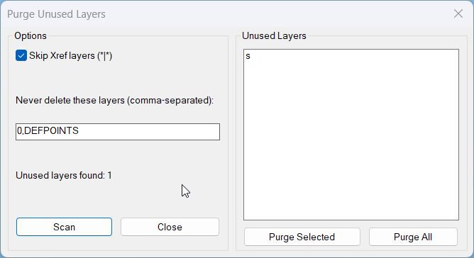
- Dialog options: toggle to Skip Xref layers that match *|* and an edit box for additional never delete layers.
- Scan: refreshes the unused layer list based on current settings and updates the status count.
- Purge Selected: deletes only the layers selected in the list box.
- Purge All: deletes all currently detected unused layers in one operation.
- Safety rules: never deletes 0, DEFPOINTS, or the current layer and can exclude Xref layers when enabled.
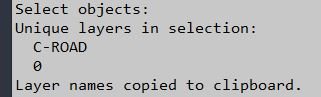
LayersNameToClipboard
- • User selection — uses ssget to collect entities; exits with a message if nothing is selected.
- • Layer extraction — iterates the selection set, calls entget, and reads (assoc 8) to obtain each entity’s layer name.
- • Deduplication — adds layer names to an in-memory list only if they are not already present (member check).
- • Reporting — prints “Unique layers in selection” and lists each layer name in the command line output.
- • Clipboard formatting — builds a single string containing only layer names separated by newline characters (one layer per line).
- • Clipboard write — calls ClipPut to copy the newline-separated list into the clipboard and prints confirmation.
- • COM cleanup — releases the temporary htmlfile object after writing to the clipboard.
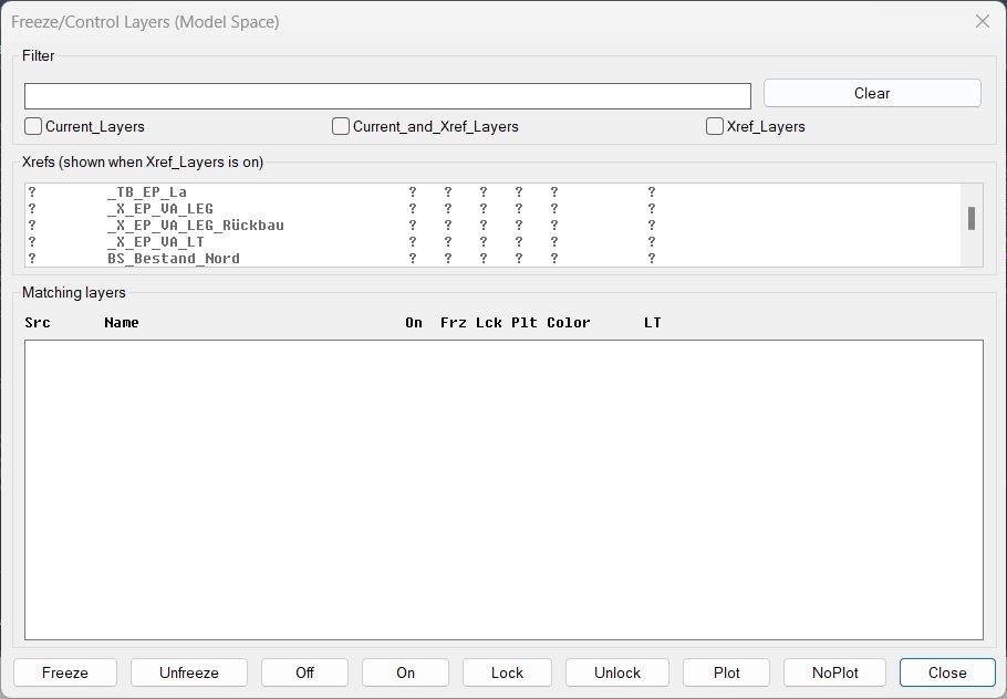
FreezeLayersInMS
- • State management — global variables track filter text, xref filter, scope toggles, selected xrefs, selected layer names, and both full/display lists for the layer list box.
- • Filter normalization — UI filter values are read as strings; a legacy "T" value is normalized to empty, preventing unexpected filter behavior/appearance.
- • Xref filter + selection — xref list is filtered by wildcard or contains-match, filled into lbXrefs, and prior selections are re-applied by index mapping.
- • Scope toggles — Current_Layers / Xref_Layers / Both determine whether matches include only non-xref layers, only xref layers (optionally limited to selected xrefs), or all layers.
- • Matching layer evaluation — a layer matches when it satisfies the name filter (wildcard or contains-match) and the scope rules (current/xref/both + selected xrefs).
- • Display vs true names — the list shows a formatted row where the layer name is displayed without xref| prefix, but selection indexes map back to the full layer names for operations.
- • Multi-select mapping — layer selections are tracked by index in lbLayers and translated back to flms3*listFull to populate flms3*selNames.
- • Batch operations — action buttons call flms3-apply which sets VLA properties on each selected layer: Freeze, LayerOn, Lock, Plottable toggles.
- • UI enable/disable — the Xref list box is enabled only when Xref_Layers or Both is selected; otherwise it is disabled via mode_tile.
- • Dialog lifecycle — writes DCL to a temp path, loads/opens dialog, wires action tiles, runs, snapshots state, unloads dialog, deletes the DCL file.
- • User feedback — after each action, prints a summary line such as Freeze applied to N layer(s).
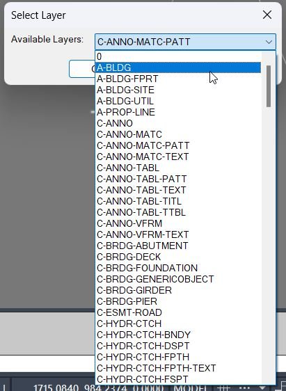
DuplicateToSelectedLayer
- • Select source entities — prompts ssget to capture the objects to duplicate; exits with a message if none selected.
- • Build layer list — enumerates all layers, removes Xref-dependent layers (*|*), sorts alphabetically, and populates a DCL popup_list.
- • Dialog defaulting — if the stored last layer exists in the list, preselects it; otherwise defaults to the first entry.
- • Temporary DCL lifecycle — writes a temp .dcl file, loads it, runs the dialog, unloads it, and deletes the file.
- • Duplicate-in-place — saves current CLAYER, sets CLAYER to the target, then runs _.COPY with base/displacement 0,0 to create duplicates without moving them.
- • Capture new entities — uses ssget "_P" to get the copied entities produced by the COPY command.
- • Assign to target layer — runs _.CHPROP on the copied entities with property LA set to the chosen layer name.
- • Bring to front — runs _.DRAWORDER on the copied entities with option _Front to adjust display order.
- • Preselect result — calls sssetfirst to make the duplicated entities the current selection for immediate follow-on operations.
- • Restore state — restores the original current layer and prints a summary including the count of duplicated entities and the target layer name.
DuplicateToNewLayer
- • Source layer detection — DUPLICATELAYER extracts source layer from the picked entity (DXF group 8); DUPLICATELAYERCURRENT uses CLAYER.
- • Dialog-driven naming — shows “Duplicate Layer” dialog with an edit box for the new name and a toggle defaulted to checked.
- • Existence check — uses tblsearch "LAYER" to determine whether the target name already exists before creating a new layer.
- • Layer creation by cloning — if missing, calls CreateLayerLike to create the new layer and copy properties from the source layer via VLA property gets/puts.
- • Set current layer — sets CLAYER to the new layer name in both commands.
- • Optional entity reassignment — for DUPLICATELAYER when the toggle is enabled, updates the entity’s layer (substitutes group 8), then calls entmod and entupd to apply changes.
- • Temporary DCL lifecycle — dialog definition is written to a temp file, loaded, used, unloaded, then the temp DCL file is deleted.
- • Validation / messaging — handles cancel/empty name/nothing selected conditions and prints status messages for created vs existing layers and assignment actions.
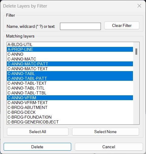
DeleteLayerByFilter
- • Embedded DCL UI — dialog includes filter edit box, multi-select list of matches, and buttons: Clear Filter, Select All, Select None, Delete, Cancel.
- • Layer candidate set — enumerates layers and excludes Xref-dependent names (*|*) and reserved layers (0, DEFPOINTS).
- • Filtering rules — empty filter shows all; wildcard filters are honored as-is; plain text is converted to *text* for “contains” matching.
- • Live list refresh — typing in the filter edit box updates the match list immediately by repopulating lb_layers.
- • Select All / None — Select All sets list_box selection to the full index range string; Select None clears the selection tile string.
- • Index parsing — on Delete, reads list_box selection indices, parses them into integers, and maps indices back to layer names.
- • Primary deletion path — attempts layer removal via -LAYDEL scripted input sequence and validates success by confirming the layer no longer exists in the table.
- • Fallback deletion path — if scripted deletion fails, attempts VLA deletion of the layer object as a last resort (typically only works if layer is deletable/empty).
- • Reporting — prints how many layers were deleted and lists failed layer names (including (reserved) and (xref) annotations when applicable).
- • Alternate command: LayDelByList — deletes layers from variable LAYLIST (must be a list of names) using the same checks and deletion pipeline, then prints Deleted/Failed summary.
ChangeLayerToSelected
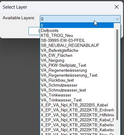
- • Layer scope — enumerates layers from the active document and excludes Xref layers by rejecting names matching *|*.
- • Temporary DCL generation — writes a dialog definition to a temp .dcl file and loads it each loop iteration.
- • Filter behavior — filter text is applied as a substring match using wcmatch against *filter* (case-insensitive); empty filter shows all layers.
- • Preselection rules — if a picked layer exists in the filtered list, it is selected; else if the last used layer exists, it is selected; otherwise the first entry is selected.
- • OK handler — captures current filter and selected popup index, resolves the layer name, saves ChangeLayer_LastFilter and ChangeLayer_LastLayer, then closes dialog with result 1.
- • Pick-from-drawing handler — closes dialog with result 2, prompts for an entity via entsel, reads group code 8 (layer), validates it exists in the non-Xref layer list, then reopens the dialog.
- • Final object selection — after OK, prompts for a multi-selection using ssget (no single-select flags), allowing window/crossing and add/remove selection gestures.
- • Apply layer change — runs _.CHPROP on the selected set and sets property LA to the chosen layer name.
- • Cleanup — unloads the dialog each loop and deletes the temporary DCL file at the end of the routine.
ChangeLayer
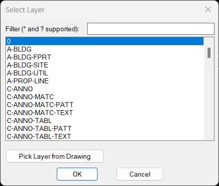
- • Visible layer enumeration — uses tblnext over LAYER and filters by flags in group code 70 to exclude Off/Frozen layers.
- • Last filter persistence — reads CHLAY-LAST-FILTER from environment; defaults to * if none; saves it back on exit.
- • Temporary DCL generation — writes a layerfilter.dcl-style file to a temp path using vl-filename-mktemp and open/write-line.
- • Wildcard filtering — uses wcmatch against the filter pattern; treats an empty filter as *.
- • Live list refresh — filter edit_box action updates filter-pat and repopulates the list box immediately.
- • Single selection tracking — list_box action stores the selected index so the chosen layer can be returned on OK.
- • Pick layer from drawing — dialog button exits with a special code (2), prompts entsel, extracts group code 8 (layer), sets filter to that layer, then reopens dialog.
- • Cleanup — unloads the dialog, deletes the temporary DCL file, and writes the last-used filter to the environment.
- • Apply current layer — c:ChangeLayer sets CLAYER to the returned layer name and prints confirmation, otherwise prints cancel/no-selection message.
MLeaderWidthFix
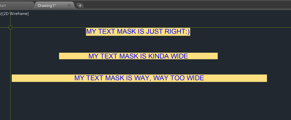
- • Selection — collects entities using ssget with filter TEXT,MTEXT,MULTILEADER; prints “No valid entities selected” if none.
- • Width measurement: TEXT — uses textbox extents and computes width from X difference of the two corners; contributes to averaging.
- • Width measurement: MTEXT — reads bounding box and computes width from ur.x – ll.x; contributes to averaging.
- • Width measurement: MLeader — only includes MLeaders with ContentType = 2 (MTEXT content) and adds TextWidth to averaging.
- • Default width — sets default to total / count if count > 0; otherwise falls back to 1.0; formats as a string with 3 decimals for the prompt.
- • User input — prompts New Width <avg>:; if user presses Enter, uses the default value.
- • Apply: TEXT — prints a message indicating TEXT width is not directly settable and skips changes.
- • Apply: MTEXT — attempts to set Width to the chosen value using a protected property write.
- • Apply: MLeader (MTEXT content) — for ContentType = 2, attempts to set TextWidth to the chosen value using a protected property write.
- • Feedback — prints Applied width: with the final numeric value.
MleaderStraight
- • DCL scope chooser — dialog offers Select MLeaders interactively (default) or All MLeaders in current space.
- • Interactive selection — attempts preselection with ssget "_I"; if none, prompts user to select MLeaders and finish with Enter; supports typical add/remove behavior depending on selection settings.
- • All-in-space selection — uses a global filter ssget "_X" restricted to current CTAB to process all MLeaders on that space/layout.
- • Per-MLeader vertex read — reads leader vertices via GetLeaderLineVertices for leader index 0, groups into 3D points, and uses the first two points as begin/end reference.
- • Choose perpendicular reference — compares ΔX vs ΔY between begin/end to decide whether to create a vertical or horizontal XLINE through the end point.
- • Project begin point — finds closest point from the begin point to that XLINE (perpendicular projection), then deletes the XLINE.
- • Rewrite leader vertices — updates leader line vertices to a two-point list (b_pt r_pt) using SetLeaderLineVertices for leader index 0.
- • Regen + report — calls Regen and prints processed count; prints “Nothing to process” if selection set is empty.
- • Robust cleanup — custom *error* handler unloads dialog, deletes temp DCL file, and reports non-cancel errors.
NCopyExtra
• Xref geometry extraction: Copies geometry out of xrefs or nested blocks into the current drawing space while preserving position and orientation. • Layer name cleaning: Automatically strips the xref prefix from layer names so copied entities end up on clean local layers (e.g. “VG_KK” instead of “_XREF|VG_KK”). • Local layer creation: Automatically creates missing local layers on the fly when they do not already exist in the drawing. • Visual property sync: Mirrors color, linetype, and lineweight from the original xref layer to the local layer to maintain the same visual appearance. • Entity relocation: New copies are placed directly on the local (non-xref) layer, making them independent from the xref reference. • Multi-pick workflow: You can keep picking objects one after another and each one will be copied and re-layered until you press Enter to finish. • Safe layer handling: Operates only on layers that actually exist and ensures new layers are properly initialized before use.
TotalLengthAreaDetailed_vs_01
Functional options in the dialog • Length or Area Radio buttons to choose whether to sum linear lengths or areas. • Excel When checked, the clipboard expression is prefixed with an equal sign for direct use in Excel. • Excel ceiling When checked, wraps the expression in a ceiling call with step 5, overriding the simple Excel option. • Place result in Acad When checked, prompts for an insertion point and creates MText showing the numeric result inside the drawing. • Decimal precision Edit box where you specify the global number of decimal places used in expressions, MText, and command line output, default value is 2.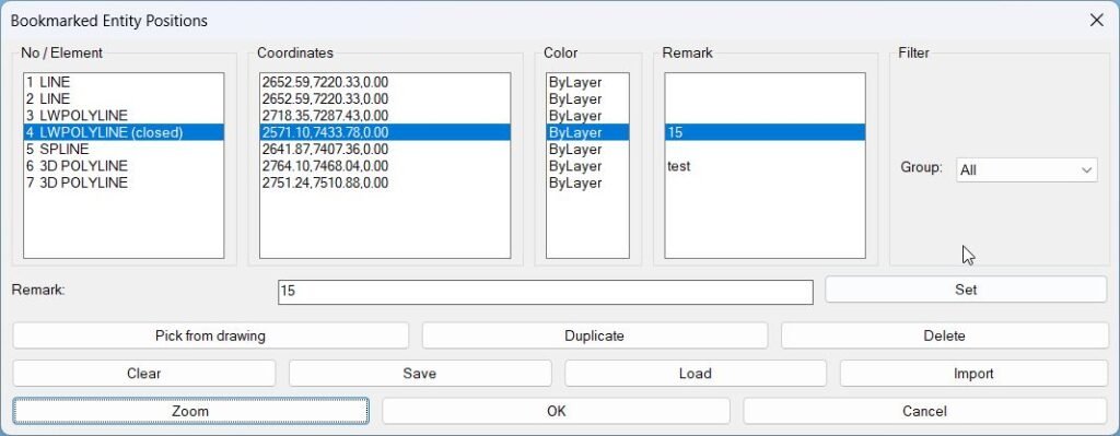
BookmarkEntities
Picking & storing bookmarks: • Button “Pick from drawing” callsbm-pick-and-storewhich: – Usesssgetwith filter(0 . "TEXT,MTEXT,LINE,LWPOLYLINE,POLYLINE,CIRCLE,SPLINE,INSERT"). – For each entity, determines: • Label – e.g. “TEXT”, “LWPOLYLINE (closed)”, “3D POLYLINE”, “BLOCK MyBlock”. • Representative start/end points via bounding box or geometry. • Color string viabm-color-string(TrueColor/aci/ByLayer/ByBlock). • Handle and entity type. – Creates an entry with empty remark""and appends it to*bm-list*.
Group / filter system: •bm-entry-groupmaps entity type to a group name: – TEXT/MTEXT → “Text”. – LINE → “Lines”. – (LW)POLYLINE → “Polylines”. – CIRCLE → “Circles”. – SPLINE → “Splines”. – INSERT → “Blocks”. – Others → “Other”. •bm-build-groupsscans*bm-list*and builds*bm-groups*=("All" ... unique group names ...). • The popup “Group” in the dialog is filled from*bm-groups*; changing it updates*bm-group*and refreshes the list. •bm-pass-filterensures only entries matching the selected group (or All) are shown.
Dialog listboxes & synchronization: • Columns are separate list boxes: – No / Element (lb_elem) – row number + label. – Coordinates (lb_coord) – bookmark start point as “X,Y,Z” (formatted using currentLUPREC). – Color (lb_color). – Remark (lb_rem). •bm-update-listrebuilds these four list boxes from*bm-list*+ current group filter, and rebuilds*bm-index-map*for “visible index → real index” translation. • Selecting in any of the list boxes forces all other list boxes to the same index and runsbm-on-select(which updates the Remark edit box).
Zoom to bookmark: • Button “Zoom” callsbm-apply-zoom: – Uses selected row inlb_elemto get visible index, then real index via*bm-index-map*, then fetches entry from*bm-list*. – Attempts to resolve the current entity by handle usinghandent. If found, recomputes the bounding box for an up-to-date zoom window (even if the object has moved). If not found, falls back to stored start/end points. –bm-make-windowbuilds a padded window around those two points (5% margin). – Callsbm-zoom-ll-ur, which usesvla-ZoomWindowto actually zoom the current view.
Remarks: • The edit box “Remark” lets you attach a free-text comment to the selected bookmark. •bm-update-remark-fieldfills the edit box when you change selection. • Button “Set” callsbm-set-remarkwhich: – Reads the current remark text. – Updates the corresponding entry in*bm-list*(usingbm-replace-nth). – Rebuilds the lists and re-selects the same visible row so the UI stays in sync.
Duplicate / Delete / Clear: • Duplicate – inserts a copy of the selected entry immediately after it in*bm-list*viabm-insert-after-nth, then refreshes the UI. • Delete – removes the selected entry from*bm-list*viabm-remove-nthand clears the remark field. • Clear – empties*bm-list*and*bm-index-map*in one shot and refreshes all list boxes.
Save / Load / Import (per-DWG persistence): • Automatic default file path:DWGPREFIX + (vl-filename-base DWGNAME) + "_BMEntityPos.lst". – This means each drawing can have its own bookmark list stored right next to the DWG (same prefix, custom suffix). • Save –bm-save-list: – Writes*bm-list*as a single LISP-readable expression into the default file (usingprin1). – Notifies with the path on success; warns if there’s nothing to save. • Load –bm-load-list: – Reads from the default per-DWG file, validates that it’s a list, assigns it to*bm-list*, and updates the dialog. • Import –bm-import-list: – Usesgetfiledto let you choose any.lstfile containing a bookmark list. – On success, replaces current*bm-list*with the imported content and updates the dialog, with a path confirmation message.Clear_Bookmarks
• Prompts user with a confirmation message • Clears the bookmark memory list when confirmed • Leaves stored data untouched if Cancel is pressed • Prints status messages to the command line after completionAdd_Bookmark
• Text handling — For TEXT and MTEXT, stores the actual string content and uses the insertion point as start, with an artificial end point offset 10 units in X • Line handling — For LINE, uses the true start point (DXF 10) and end point (DXF 11) and labels it as “LINE” • Polyline handling — For LWPOLYLINE and POLYLINE, labels as “POLYLINE” and uses bounding box corners from getboundingbox • Circle handling — For CIRCLE, uses the center (DXF 10) and a corner computed from center plus radius in X and Y, labels as “CIRCLE” • Spline handling — For SPLINE, uses DXF 10 and 11 as start and end points, labels as “SPLINE” • Block handling — For INSERT, uses the block name (DXF 2) prefixed with “BLOCK: ” and uses insertion point plus an X-offset as end point • Fallback case — For unknown types, labels as “UNKNOWN” with zeroed points to avoid nil values • Selectable accumulation — Multiple runs keep pushing new bookmarks into *textPositions* instead of overwriting itRenameBlock
- 🚀 Rename selected block — select a block reference in the DWG and rename its block definition directly.
- 🔍 Use preselected block — if exactly one block is already selected, the command can use that block immediately.
- 🧩 Dynamic block awareness — reads
EffectiveNamewhen available for dynamic block references. - 🔒 Xref exclusion — avoids renaming external reference definitions that should not be handled like normal blocks.
- 📝 Editable default name — opens the current block name as the default value in
lisped. - 🔴 Duplicate-name prevention — rejects new block names that already exist in the current drawing.
- 📌 Selection highlight — highlights the chosen block during the command so the user can confirm the target visually.
- 🔄 Undo mark support — groups the rename operation for cleaner AutoCAD undo behavior.
- 🧹 Command-line cleanup — temporarily suppresses command echo during the rename operation.
- 🏷️ DWG block management — useful for cleaning, standardizing, and organizing AutoCAD block libraries in production drawings.
RemovesDuplicatedBlocks
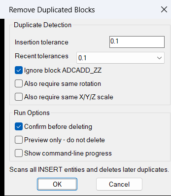
- 🚀 Run duplicate block cleanup – use
REMDUPto scan the DWG and remove stacked duplicate block references. - 🔍 Scan all block references – automatically detects all
INSERTobjects in the active drawing. - 🧩 Match duplicates by block name – avoids deleting unrelated blocks that are close together but have different names.
- 📌 Compare insertion locations – identifies duplicate blocks based on nearly identical insertion points.
- 🔢 Use fixed tolerance cleanup – applies a
0.1drawing-unit distance threshold for duplicate detection. - 🧹 Delete duplicate block references – removes extra repeated blocks while keeping the original processed reference.
- 🔒 Skip protected block name – excludes
ADCADD_ZZfrom cleanup processing. - 🔄 Support AutoCAD undo – groups the cleanup operation with an undo mark for safer editing.
- 📊 Show cleanup summary – displays how many blocks were processed and how many duplicates were deleted.
- 🧰 Improve DWG quality control – helps reduce duplicate symbols, repeated markers, and unnecessary block clutter in AutoCAD and Civil 3D drawings.
- 🚀 Run duplicate block cleanup – use
CopyBlock
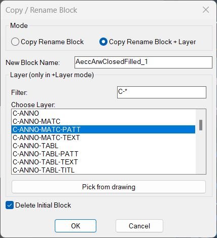
• Copy and rename in one step: Creates a new block definition, copies geometry, and assigns a new name while leaving the original definition intact. • Two working modes: Simple “Copy Rename Block” mode, or an extended “Copy Rename Block + Layer” mode with full layer control and filtering. • Interactive layer selection: In +Layer mode, you can filter layer names, select from a list, or pick any object in the drawing to adopt its layer. • Content normalization: Optionally forces all entities in the new block definition to a single layer and ByLayer display properties for consistent behavior. • Safe naming strategy: Automatically proposes a unique default name and prevents invalid or duplicate block names from being used. • Delete original toggle: You can decide whether the original block reference is kept or automatically deleted after the new one is created and linked. • Locked layer protection: Rejects block references placed on locked layers to avoid unintended edits in protected areas. • Version aware: Uses the AutoCAD version to connect to the correct ObjectDBX interface for reliable operation across releases.ChangeBlockEntitiesLayer
• Multiple block support: Processes all block references included in the selection set in one execution of the command. • Definition based edit: Modifies the block definition itself, so every instance of that block in the drawing reflects the updated internal layers. • Layer unification: Ensures that geometry inside the block uses the same layer as the block reference, improving control over visibility, color, and plotting through the block layer. • Property safe: Only objects that actually expose a Layer property are modified, preventing errors on unsupported objects inside the definition. • Case insensitive compare: Compares layer names in a case insensitive way so layers that differ only by letter case are recognized as identical. • No geometry duplication: Edits existing definition entities in place instead of creating new geometry, keeping the drawing clean.3D_PolyOffset
- 3D polyline vertex extraction.
- Temporary 2D polyline generation.
- Keyboard-driven offset distance input.
- Automated 2D offset operation.
- Reconstruction of a 3D polyline with preserved elevation values.
- Automatic cleanup of intermediate geometry.
- System variable state preservation and restoration.
SetPlotDeviceNames_00
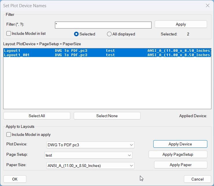
- • Target device selection — sets desired device string to DWG To PDF.pc3.
- • Enumerate layouts — iterates all layouts in the active drawing using vlax-for over the Layouts collection.
- • Refresh device info — calls vla-RefreshPlotDeviceInfo to ensure device list is current.
- • Case-insensitive validation — uppercases both the target device and the returned device list for reliable matching.
- • Assign plot config — if present, sets ConfigName for the layout to the target device.
- • Per-layout warning — if missing, prints Plot device ‘DWG To PDF.pc3’ not available for layout: <layout name>.
SteSysVar
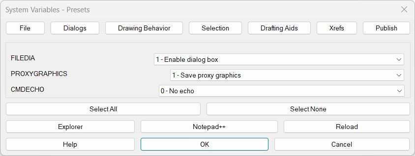
Main Functionalities: • Tabbed SYSVAR editor — variables are grouped by use (File, Dialogs, Drawing Behavior, Selection, Drafting Aids, Xrefs, Publish). • Dropdown-based presets — each system variable shows the recommended / preset value first, followed by documented alternatives (e.g. DIMASSOC, AUTOSNAP, SELECTIONPREVIEW). • Select All / Select None per tab — set all vars on the current tab to preset (index 0) or to 0 when available, with one click. • Integrated Help panel — shows a generated list of all variables with their meanings; user can copy selected or all to clipboard. • Path-aware tools — buttons to open the folder, open the LISP in Notepad++, or reload the LISP without restarting AutoCAD. • Publish tab — extra tab specifically forPUBLISHCOLLATEto control publish collation from the same UI. • Dedicated publish entry point — commandc:SteSysVarPublishjumps directly to the Publish tab.
Hide / Show Objects
Main Functionalities: • Dialog-driven visibility control — Choose from isolate, hide, or show-all directly via a simple UI. • Remembers last selection — Automatically selects the last used option on the next run. • Dynamic DCL creation — Builds its dialog at runtime without needing an external DCL file. • Automatic screen refresh — Uses “_regen” after every visibility change to update the display.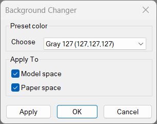
Change Background Color
Main Functionalities: • Dialog UI (c:BG / c:BGDCL) — Interactive color picker with Apply, OK, and Cancel buttons. • Quick Commands — Includes c:BGGrey, c:BGWhite, c:BGBlack for instant background changes. • Toggle Command — c:bgt switches Model space background between black and white. • Contrast Adjustment — Automatically sets cursor, tracking vector, and snap marker colors based on background brightness. • Snapshot & Restore — Keeps original color settings safe until the user confirms changes.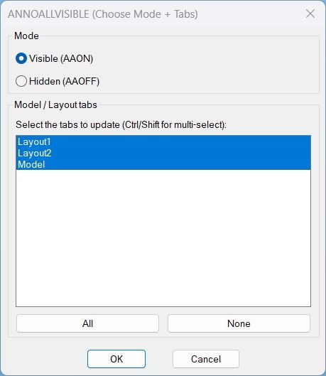
AnnoAllOnOff
- • Embedded DCL is written to a temp file at runtime and loaded to display a single configuration dialog.
- • Mode selection via radio buttons: Visible (AAON) sets value 1, Hidden (AAOFF) sets value 0.
- • Multi-select tab picker allows choosing any combination of Model/Layout tabs to update.
- • All selects all tabs using a generated index string, and None clears selection to prevent changes.
- • Per-tab application switches CTAB for each selected tab and applies ANNOALLVISIBLE to the chosen value.
- • Layout handling forces paperspace on layout tabs by setting MSPACE to false when in a layout context.
- • State restoration restores CTAB, TILEMODE, and MSPACE after execution.
RotateUCS
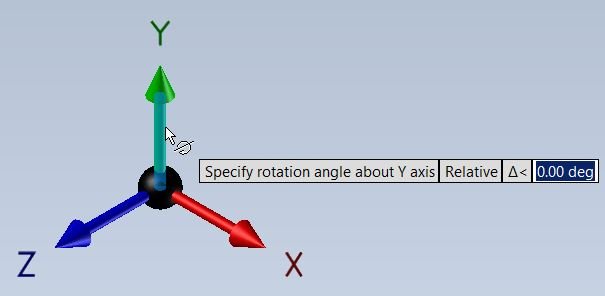
Main Functionalities: • Rotate UCS around Z by a user-defined angle. • Auto-reset snap angle to 0 so the drafting angle matches the UCS. • Start from World UCS every time to avoid cumulative rotation errors. • Display the final angle to the user for confirmation. • Optionally save the rotated UCS under a custom name for later reuse.
NavvCubeDisplayOffOn
[‘🚀 Provides one command-line entry point named NavvCubeDisplayOffOn.’, ‘🧭 Controls the AutoCAD navigation cube display state through NAVVCUBEDISPLAY.’, ‘🔄 Sends NAVVCUBEDISPLAY 1 followed by NAVVCUBEDISPLAY 3 to reset the display state.’, ‘🧰 Uses the active AutoCAD document and vla-sendcommand for command execution.’, ‘⚡ Runs without a dialog, without selection prompts, and without drawing geometry edits.’, ‘🖥️ Helps restore navigation cube visibility after workspace changes, display issues, or screen setup adjustments.’, ‘📌 Keeps the workflow simple for CAD production users who need a fast visual navigation reset.’, ‘🔒 Leaves model-space entities, layers, blocks, xrefs, and Civil 3D objects unchanged.’]
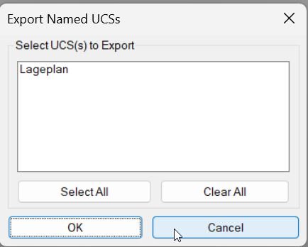
Export_Import_MS_UCS
✅ 📤 Export named UCS definitions from the active AutoCAD drawing to a portable .ucs file.
✅ 📥 Import named UCS definitions from a previously exported .ucs file into the current drawing.
✅ 🧭 Transfer model-space coordinate systems between DWG files without manually recreating UCS origin and axis settings.
✅ 🗂️ Use AutoCAD file dialogs for selecting save and import locations.
✅ 💾 Remember the last-used folder path across sessions through the Windows Registry.
✅ 🏗️ Default to the current drawing folder when no previous UCS export/import folder exists.
✅ 🔁 Handle duplicate UCS names on import by generating unique names instead of overwriting existing UCS records.
✅ 🧱 Use UCS table records, entmake, tblnext, tblsearch, open, read-line, write-line, and Visual LISP file operations.
✅ 📐 Support CAD production workflows where UCS definitions must be reused across project drawings, xrefs, Civil 3D sheets, and model-space layouts.
✅ 🧰 Keep export and import workflows simple with dedicated command aliases for dialog-based and raw file-path execution.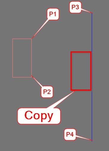
CopyMove2MidPoint_vs.01
✅ Select multiple AutoCAD drawing objects for midpoint-based relocation.
📐 Define a source midpoint using two picked reference points.
🎯 Define a destination midpoint using two picked reference points.
🔄 Move selected entities with MMid2.
📋 Copy selected entities with CMid2.
🌐 Respect the active UCS by transforming base point and vector data to WCS.
🔒 Skip objects located on locked layers.
🧰 Use a single shared engine for move and copy behavior.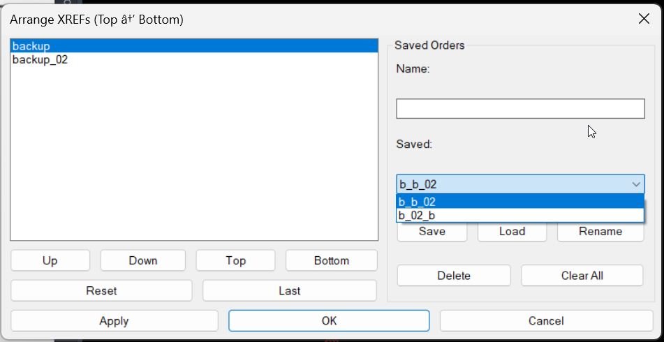
XrefDrawingOrder
🚀 Open a dedicated XREF ordering dialog with MXR or MXR_DCL.
📋 Automatically list xrefs found in the active drawing.
⬆️ Move selected xrefs upward in the display order.
⬇️ Move selected xrefs downward in the display order.
🔝 Send an xref to the top of the ordering list.
🔻 Send an xref to the bottom of the ordering list.
🔄 Reset the list to the current xref collection.
🕘 Reload the last applied xref order stored in the drawing.
💾 Save named xref order presets for repeated use.
📂 Load saved order presets and fill missing current xrefs automatically.
✏️ Rename saved presets from the DCL dialog.
🗑️ Delete selected saved presets or clear all saved presets.
✅ Apply the draw order while keeping the dialog open for iterative testing.
🟢 Use OK to apply the order and close the dialog.
🔴 Use Cancel to close without applying changes.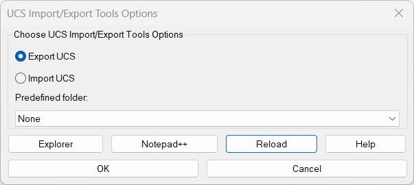
ExpImpUCS
✅ 📤 Export all named UCS definitions from the active drawing to a reusable .ucs text file.
✅ 📥 Import named UCS definitions from an external .ucs file and rebuild them in the active AutoCAD drawing.
✅ 🧭 Store UCS data as origin, X-axis point, and Y-axis point for reliable coordinate system reconstruction.
✅ 🔄 Update existing UCS definitions instead of blindly duplicating names.
✅ 🧮 Normalize and validate UCS vectors before writing them to the UserCoordinateSystems collection.
✅ 🗂️ Use predefined project folders for fast access to UCS_Lageplan directories.
✅ 🔍 Discover OneDrive project roots from environment variables, registry values, and user profile OneDrive folders.
✅ 🧰 Use a DCL dialog for Export UCS, Import UCS, predefined folder selection, help, reload, Explorer, and Notepad++ actions.
✅ 📋 Copy help text, selected help lines, and current path information to the clipboard.
✅ 🔤 Toggle Unicode help output for better compatibility with older AutoCAD or Windows clipboard behavior.
✅ 🧹 Skip empty, comment, malformed, or invalid UCS import lines safely.
✅ 🧱 Keep the user workflow focused on UCS setup, coordinate transfer, CAD standardization, and drawing preparation.AreaCalc
🚀 Starts with the AC command from the AutoCAD command line.
🔍 Provides an object filter for ANY, POLYLINE, CIRCLE, ELLIPSE, REGION, SPLINE, and HATCH.
📐 Calculates individual and total area from closed area-capable entities.
🧭 Uses bounding boxes to place area labels near the center of each selected object.
🏷️ Allows a custom label prefix and starting number.
🔢 Supports decimal precision settings from 0 to 8, with LUPREC fallback.
🧮 Converts from drawing units to selected target area units.
➕ Supports an optional additional conversion column.
🔗 Can build AutoCAD field expressions for linked area values when field mode is enabled.
📊 Outputs to LineText, AutoCAD Table, TXT, or CSV.
💾 Creates TXT and CSV area reports and opens the output file location automatically.
↩️ Wraps the operation in an AutoCAD undo mark and restores CMDECHO after completion.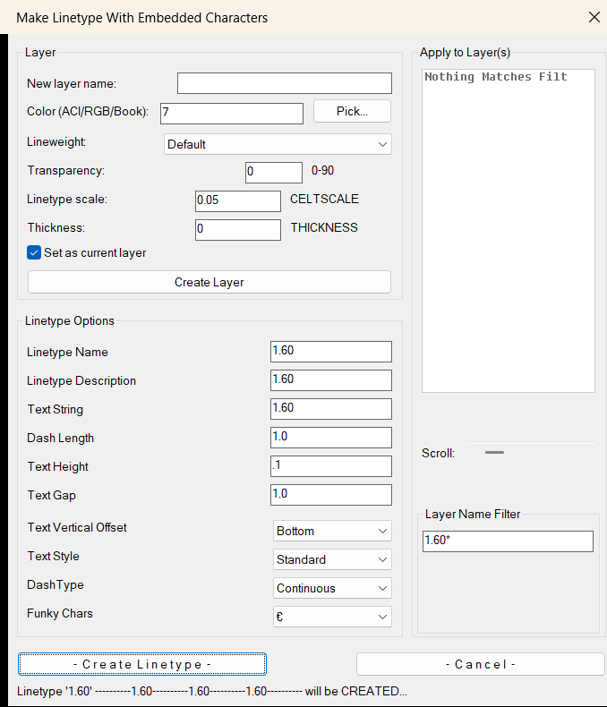
LinetypeWithCharacters2
🚀 Launches a DCL-based linetype builder with the MAKELT2 command.
🔤 Creates or redefines AutoCAD linetypes with embedded text strings.
📐 Controls dash length, dash pattern, text height, text gap, vertical offset, and text style.
✨ Provides a Funky Chars dropdown for inserting special characters into the linetype text string.
🎨 Creates or updates layers with ACI, RGB, or Color Book color values.
🖱️ Supports Pick color using AutoCAD TrueColor or Color Index dialogs.
📏 Applies layer lineweight from a predefined lineweight list.
🟦 Applies transparency values from 0 to 90.
⚙️ Sets CELTSCALE and THICKNESS defaults for the created layer workflow.
📌 Optionally sets the created layer as the current layer.
📂 Applies the generated linetype to one layer or multiple selected layers.
🔍 Includes layer filtering and horizontal scroll handling for long layer names.
💾 Remembers common linetype and layer defaults in the Windows registry.
🔄 Regenerates the drawing after successful linetype assignment.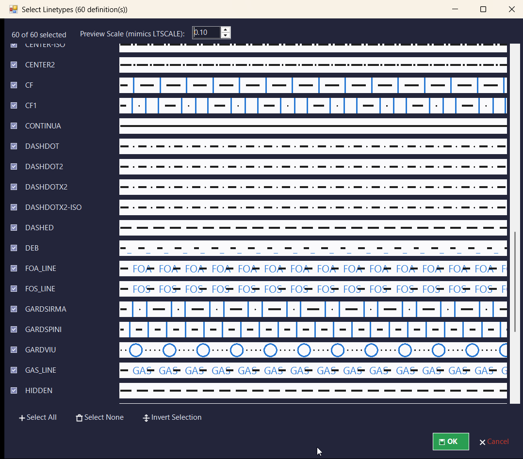
LinFileDraw_vs.01
🚀 Embedded DCL interface for selecting a LIN file and controlling the full drawing workflow.
📂 Browse and refresh support for external *.LIN linetype definition files.
🔍 Automatic parsing of linetype names from LIN definitions.
✅ Multi-select linetype dialog with Select All, Select None, and Invert actions.
📐 Draws one sample LWPOLYLINE row per selected linetype.
🏷️ Creates MText labels showing the linetype name, the layer name, or both.
📊 Adjustable sample length, row step, linetype scale, text height, line-to-label gap, and label-to-label gap.
🎯 Start point can be typed manually or picked from the drawing.
🧭 Current UCS support for point picking, sample geometry, row layout, and text orientation.
🧱 Output layer modes include layer per linetype, current layer, or selected existing layer.
🟢 Automatic layer creation when using the layer-per-linetype mode.
🔄 Draw, Apply, Undo, OK, and Cancel workflow for iterative testing.
💾 Persistent CFG memory for accepted settings and dialog positions across AutoCAD restarts.
🛡️ Safe linetype loading with skipped-item reporting when a linetype cannot be loaded.
⚠️ Reports common LIN loading problems, including missing SHX shape or font files.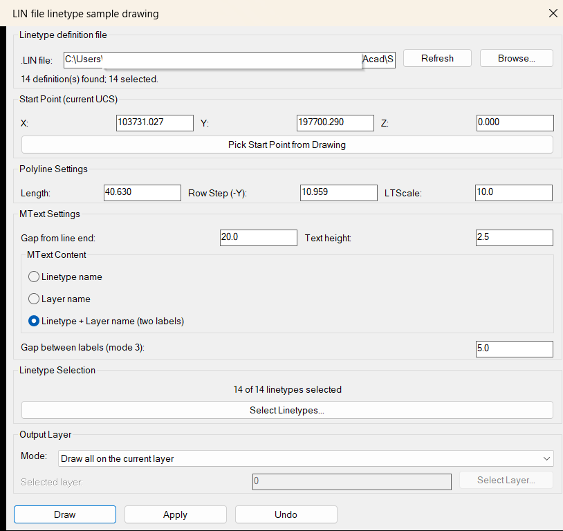
LinFileDraw
🚀 Embedded DCL interface for selecting a LIN file and controlling the full drawing workflow.
📂 Browse and refresh support for external *.LIN linetype definition files.
🔍 Automatic parsing of linetype names from LIN definitions.
✅ Multi-select linetype dialog with Select All, Select None, and Invert actions.
📐 Draws one sample LWPOLYLINE row per selected linetype.
🏷️ Creates MText labels showing the linetype name, the layer name, or both.
📊 Adjustable sample length, row step, linetype scale, text height, line-to-label gap, and label-to-label gap.
🎯 Start point can be typed manually or picked from the drawing.
🧭 Current UCS support for point picking, sample geometry, row layout, and text orientation.
🧱 Output layer modes include layer per linetype, current layer, or selected existing layer.
🟢 Automatic layer creation when using the layer-per-linetype mode.
🔄 Draw, Apply, Undo, OK, and Cancel workflow for iterative testing.
💾 Persistent CFG memory for accepted settings and dialog positions across AutoCAD restarts.
🛡️ Safe linetype loading with skipped-item reporting when a linetype cannot be loaded.
⚠️ Reports common LIN loading problems, including missing SHX shape or font files.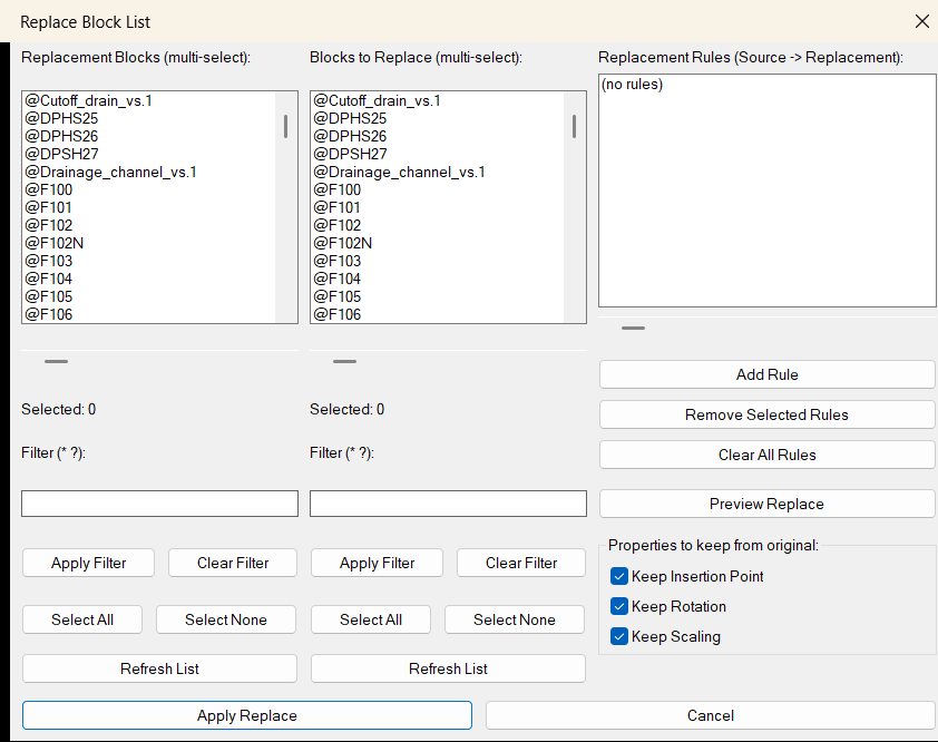
ReplaceBlockList
- 🚀 Launches a dedicated AutoCAD DCL dialog with the
ReplaceBlockListcommand. - 🧱 Lists available non-xref, non-layout, non-anonymous block definitions from the active drawing.
- 📌 Provides two multi-select panels: replacement blocks on the left and source blocks to replace on the right.
- 🔍 Supports wildcard filtering with patterns such as
*and?for both block lists. - ☑️ Includes Select All, Select None, Clear Filter, Apply Filter, and Refresh List controls for each panel.
- 📋 Builds multiple replacement rules in the format
SourceBlock -> ReplacementBlock. - 🧠 Pairs selected blocks by list index, so replacement selection 1 maps to source selection 1.
- 🛑 Skips invalid rules where the source and replacement names are the same.
- 🛡️ Skips duplicate source rules to avoid replacing the same source block twice in one run.
- 👁️ Previews every rule with the number of source instances that will be affected.
- 📐 Preserves insertion point when the Keep Insertion Point toggle is enabled.
- 🧭 Preserves block rotation when the Keep Rotation toggle is enabled.
- 📏 Preserves effective X, Y, and Z scale when the Keep Scaling toggle is enabled.
- 🔄 Uses the first inserted replacement block reference as the template for new copies.
- 🧹 Deletes old source block references after the replacement copy is created.
- ↩️ Wraps the apply operation in an AutoCAD undo mark for easier rollback.
- 💾 Remembers filters, rules, and preserve toggles in
ReplaceBlockList.cfg.
- 🚀 Launches a dedicated AutoCAD DCL dialog with the
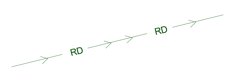
ExplodeLinetype
– Runs the complete standardized workflow with the ExplodeLinetype command.
– Provides LINEXP as the underlying text-explosion command.
– Converts selected AutoCAD TEXT objects into editable line geometry.
– Converts selected AutoCAD MTEXT objects into editable line geometry.
– Excludes leader-associated text identified through ACAD_REACTORS data.
– Filters selected objects located on locked layers through the Express Tools selection-set helper.
– Detects AutoCAD groups containing selected text and removes the text members before conversion.
– Calculates text bounding boxes and expands the current view when selected objects are not fully visible.
– Temporarily unlocks a locked current layer and restores its locked state after processing.
– Temporarily unlocks a locked viewport when zoom adjustment is required and restores the viewport lock afterward.
– Mirrors selected text before WMF export and mirrors imported geometry back into its original orientation.
– Exports selected text to a temporary txtexp.wmf file.
– Erases the original selected text only after the temporary WMF file is successfully created.
– Imports the WMF representation as exploded drawing geometry.
– Restores the previous view after temporary zooming.
– Reports how many selected objects were exploded to lines.
– Assigns the resulting previous selection set to the MISC layer.
– Sets the resulting geometry color to ByLayer.
– Sets the resulting geometry linetype to Continuous.
– Sets the resulting geometry lineweight to ByLayer.
– Requires the active view to be a plan view with view direction 0,0,1.
– Loads and depends on AutoCAD Express Tools when available.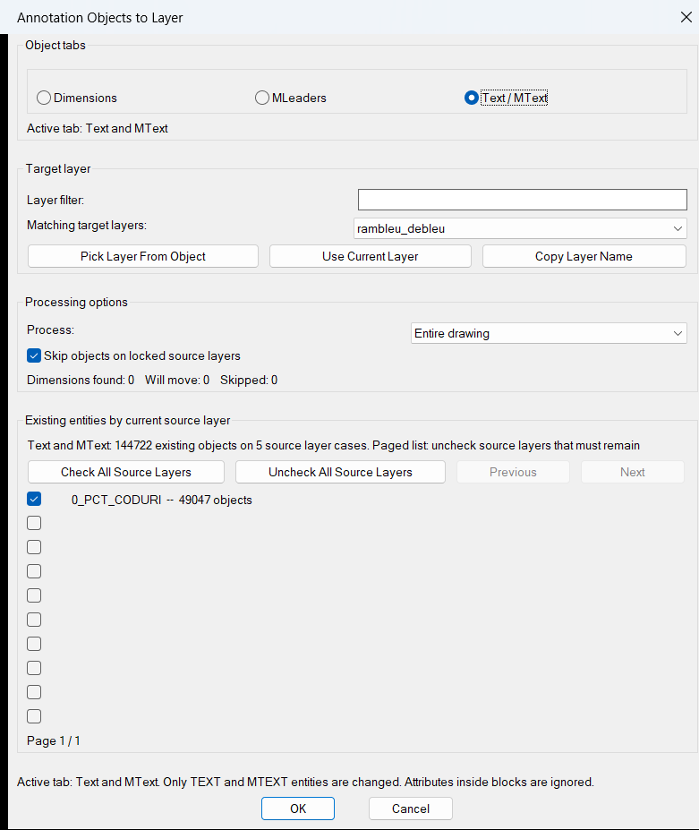
Entities2Layers
– Opens the Annotation Objects to Layer DCL dialog with ENTITIES2LAYERS or E2L.
– Provides separate Dimensions, MLeaders, and Text / MText object tabs.
– Processes DIMENSION entities from the Dimensions tab.
– Processes MULTILEADER entities from the MLeaders tab.
– Processes TEXT and MTEXT entities from the Text / MText tab.
– Filters the target-layer popup list using user-entered text.
– Lets the user select a target layer from the list, pick a layer from an object, or use the current layer.
– Excludes xref-dependent layers from the available target-layer list.
– Copies the selected target-layer name to the Windows clipboard through PowerShell.
– Supports Entire drawing, Current layout, Model space only, and Paper space layouts scopes.
– Displays matching source layers with per-layer object counts.
– Provides a ten-row paged source-layer checklist with Previous, Next, Check All, and Uncheck All controls.
– Marks locked source layers and the selected target layer in the source-layer list.
– Lets users exclude individual source layers from processing.
– Optionally skips objects on locked source layers.
– Shows live found, will-move, skipped, locked, and disabled-source counts.
– Uses an O(n log n) sort-and-group counting pass instead of repeated association-list updates.
– Derives live totals from the current source-layer case list and avoids a second full entity scan during each dialog interaction.
– Performs the final full entity collection only after the user accepts the dialog.
– Protects each source-layer row update and stored checkbox state with named guarded handlers.
– Validates source-row limits, source-case data, and persisted dialog coordinates before using them.
– Persists the selected category, layer filter, target layer, scope, locked-layer option, source-layer states, and dialog position.
– Uses guarded callbacks and per-entity error handling so unreadable entities are skipped instead of crashing the dialog.
– Stops safely without drawing changes when dialog initialization cannot be completed.
– Changes the entity layer through DXF group code 8 and refreshes each modified entity.
– Wraps the move operation in an AutoCAD undo mark.
– Reports found, moved, skipped, locked, and failed counts at the command line.AutoTrimExtendLines
✅ Key functionalities:
🚀 DCL-based trim and extend control panel for AutoCAD and Civil 3D.
📐 Three operation modes: Trim only, Extend only, and Trim and Extend.
🧱 Separate selection workflow for bounding edges and objects to modify.
🔍 Supported bounding edges include LINE, LWPOLYLINE, POLYLINE, ARC, CIRCLE, SPLINE, and ELLIPSE.
✏️ Supported editable objects include LINE, LWPOLYLINE, POLYLINE, ARC, and SPLINE.
🟡 Live selection highlighting with redraw mode 3 and highlight cleanup with redraw mode 4.
🔄 Apply button processes edits and reopens the dialog with selections preserved.
↩️ Undo Last button reverses the last operation using AutoCAD UNDO 1.
🧾 Debug log list inside the dialog shows processed objects, intersections, distances, modified counts, and skipped objects.
📋 Copy Log to Clipboard exports the debug log for troubleshooting and documentation.
💾 Dialog position memory stores the last DCL window location during the AutoCAD session.
🧹 Temporary DCL file is created, loaded, unloaded, and deleted safely on every dialog loop.
🔒 Error handling clears highlights, unloads the dialog, deletes temp files, and ends undo marks safely.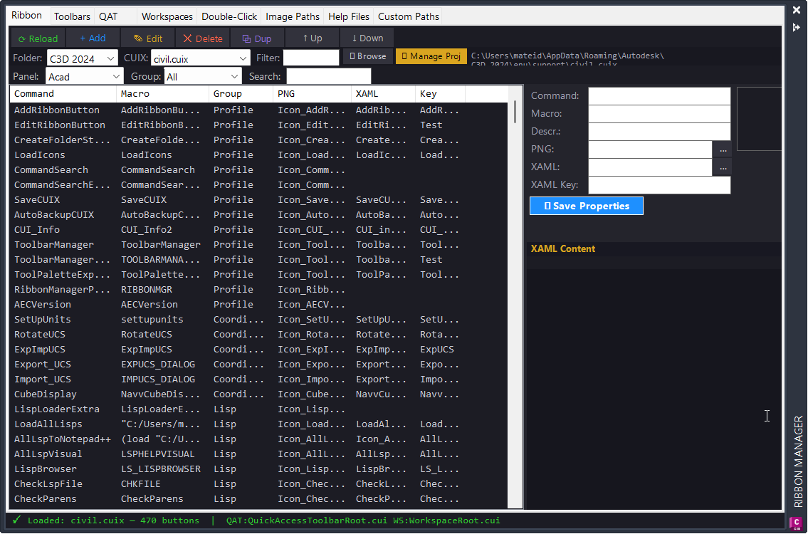
ToolPaletteExporter
– Opens a DCL-based Tool Palette Exporter interface.
– Lists discovered XTP palettes with wildcard filtering and horizontal scrolling.
– Supports multi-selection, select all, select none, and copy palette list actions.
– Exports selected palettes to ZIP archives named PaletteName_export.zip.
– Includes the original XTP file in the archive.
– Includes the matching PaletteName_2 image folder when it exists.
– Groups found referenced source files by file extension under Source_Files.
– Writes Files_not_found.csv for missing source-file references.
– Displays a missing-file report dialog when unresolved paths are found.
– Copies missing-file and diagnostic reports to the Windows clipboard.
– Adds custom XTP folders and saves them in the registry.
– Remembers the last output folder, filter, and selected palettes.
– Provides TPE_DIAG for troubleshooting AutoCAD ToolPalettePath, OneDrive detection, and XTP discovery.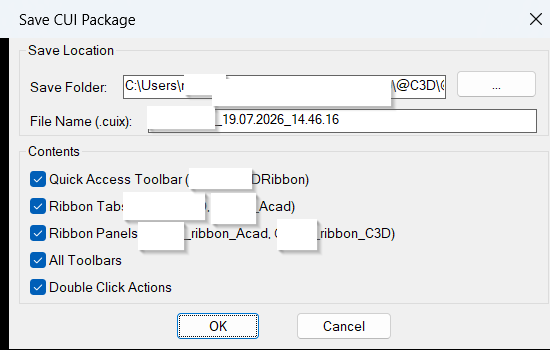
SaveCUIX
Finds CIVIL.cuix automatically using AutoCAD search paths.
Creates a temporary DCL dialog with save folder, file name, and content toggles.
Builds default output names using [username]C3D_ plus a timestamp.
Lets the user include or exclude Quick Access Toolbar, ribbon tabs, ribbon panels, toolbars, and double-click actions.
Extracts the CUIX package to a temporary working folder.
Filters RibbonRoot.cui to keep only the target [username] ribbon tabs and panels.
Filters QuickAccessToolbarRoot.cui to keep only [username]_C3DRibbon when enabled.
Clears ToolbarRoot.cui when toolbar export is disabled.
Clears DoubleClickRoot.cui when double-click action export is disabled.
Repacks the filtered files into a new .cuix file.
Uses a done file to report OK, ERROR, or timeout status back to AutoCAD.LoadIcons
- 📁 Recursively scans the configured AutoCAD Help_File folder tree.
- 🖼️ Copies only files matching
Icon_*.png. - 🚫 Skips folders named
ssso screenshot folders are not processed. - 🔄 Overwrites existing destination icon files with the latest matching source files.
- 📌 Copies all icons into the Civil 3D 2024 support Icons folder.
- 🧩 Searches for
CIVIL.cuixand reloads it to refresh ribbon icon references. - 📊 Displays the total number of copied icon files in the command line and completion alert.
- ⚙️ Provides
LoadAllIconsas a simple alias for the same icon loading workflow.
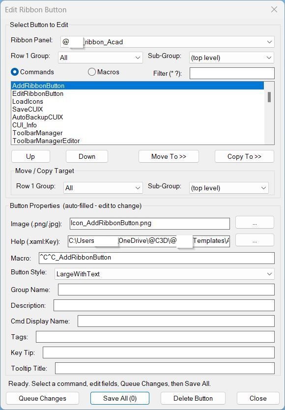
EditRibbonButton
- 🧰 CUIX ribbon command editor for custom AutoCAD and Civil 3D ribbon panels.
- 🔍 Automatic CUIX discovery by scanning support-directory CUIX files for
[username]_ribbon_*ribbon panel definitions. - 📂 Ribbon panel, group, and subgroup navigation for editing commands inside folded panels, split buttons, and top-level groups.
- 🧠 Command and macro mode for browsing ribbon buttons by command name or underlying menu macro string.
- 🏷️ Wildcard filtering with
*and?to quickly locate commands or macros. - 🎨 Image assignment for small and large ribbon images using PNG or JPG file references.
- 📘 XAML help linking with
ExtendedHelpFileandExtendedHelpKeysupport, including a key picker for tooltip ResourceDictionary entries. - 📝 Metadata editing for macro, button style, group name, description, command display name, tags, key tip, and tooltip title.
- 📌 Button ordering tools to move commands to top, up, down, or bottom within the active row.
- 🔄 Move and copy tools for transferring ribbon buttons to another group or subgroup.
- 🧹 Delete button workflow for removing selected ribbon commands from the CUIX structure.
- 📤 Queue, Apply, and Save All workflow for batching edits before writing changes to the CUIX file.
- 🔐 Timestamped CUIX backup before every direct CUIX modification.
- 🧩 Debug command to inspect CUIX resolution, cached structure, support-directory files, and reload readiness.
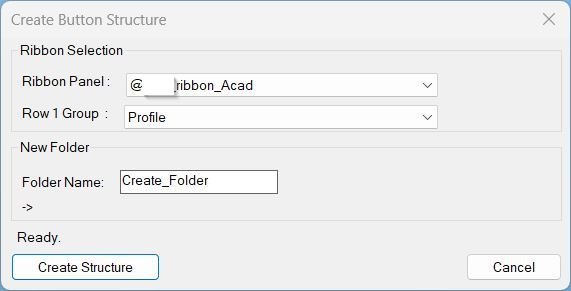
CreateFolderStructure
– Scans CIVIL.cuix from the AutoCAD search path.
– Extracts ribbon panels whose names match [username]_ribbon_*.
– Reads Row 1 groups, split buttons, folded panels, command buttons, and toggle buttons from RibbonRoot.cui.
– Displays a DCL dialog titled Create Button Structure.
– Lets the user select the target ribbon panel and Row 1 group.
– Provides a folder-name input for the new command/help item.
– Shows a live computed target path before creating files.
– Maps [username]_ribbon_Acad directly to the main Help_File folder.
– Maps [username]_ribbon_XXX to Help_File\XXX.
– Creates the final folder as {RibbonBase}\{Group}_menu\{Name}.
– Creates a blank Icon_{Name}.png file.
– Creates a blank {Name}.lsp file.
– Copies the configured XAML model template to {Name}.xaml.
– Replaces x:Key=”Test” with x:Key=”T{Name}” in the generated XAML file.
– Creates ss\ss_00, ss\ss_01, ss\ss_02, and ss\ss_03 folders.
– Creates vlx_fas\vlx_fas_00, vlx_fas\vlx_fas_01, vlx_fas\vlx_fas_02, and vlx_fas\vlx_fas_03 folders.
– Persists last-used ribbon, group, and folder name between runs.
– Uses unique temporary DCL, PowerShell, and done-file names based on the AutoCAD DATE value.
– Includes a CBS_Diag command for troubleshooting path setup, template availability, CUIX detection, and cached data.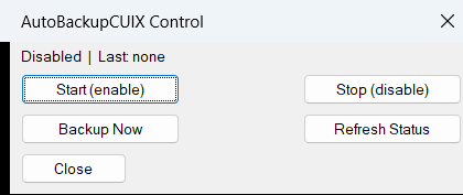
AutoBackupCUIX
Key functionalities:
– Automatic daily backup at 17:00 using ABC:HOUR and ABC:MINUTE settings.
– Manual Backup Now command for immediate CUIX protection.
– Start and Stop commands for enabling or disabling the command reactor.
– Status command showing enabled state, reactor state, configured schedule, save path, and last backup date.
– DCL control dialog generated in the Temp folder for non-command-line operation.
– CIVIL.cuix discovery using findfile, so the active AutoCAD support path is used.
– Timestamped output file names for versioned backup history.
– Hidden PowerShell execution using a VBS launcher to avoid a visible console window.
– CUIX archive extraction and rebuild using System.IO.Compression.FileSystem.
– RibbonRoot.cui filtering that keeps [username]_ribbon_Acad, [username]_ribbon_C3D, [username]_C3D, and [username]_Acad ribbon definitions.
– Done-file reporting for OK, error message, or timeout feedback.
– Auto-start integration through s::startup so the backup reactor can enable when AutoCAD starts.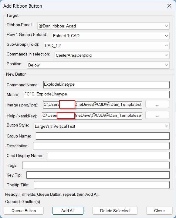
AddRibbonButton
Reads loaded CIVIL.cuix ribbon data. Lists @Dan_ribbon_* ribbon panels, All groups, folded panels, sub-groups, and existing commands. Adds new RibbonCommandButton nodes below or above a selected reference command. Supports queueing several buttons before applying. Creates MenuMacro entries with macro text, command display name, description, tooltip metadata, image paths, and extended XAML help content. Auto-completes image paths and XAML help keys. Provides button styles including LargeWithText, LargeWithVerticalText, Large, SmallWithText, and SmallWithoutText. Can delete selected ribbon command buttons. Writes logs and diagnostic files to TEMP\ARB_Patch. Reloads CIVIL.cuix after successful patching.
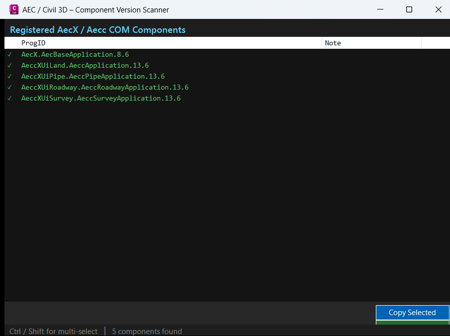
AECVersionPlugin
- 🚀 AutoCAD .NET plugin build setup – prepares a managed DLL project for loading into AutoCAD and Civil 3D.
- 🔧 Command-ready reference structure – includes
accoremgd,acdbmgd, andacmgdreferences needed by typical AutoCAD commands. - 📐 64-bit platform targeting – configures
x64so the DLL matches the AutoCAD runtime architecture. - 🧩 Visual Studio friendly configuration – uses C# language version 9.0 and a clean SDK-style project file.
- 🪟 Windows Forms support – allows dialog-based version scanners, diagnostic panels, and result windows.
- 📦 Copy Local disabled – keeps Autodesk DLL references external so AutoCAD loads its own runtime assemblies.
- 📌 Documented loading workflow – notes the expected
NETLOADandAECVERSIONusage path directly in the project comments.
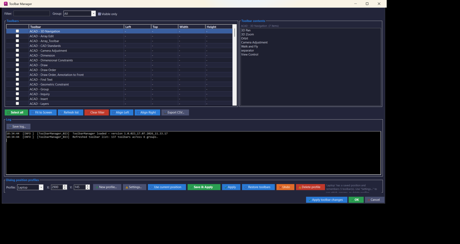
ToolbarManager_vs.01
- 🚀 Open toolbar manager – run
TOOLBARMANAGER_023to launch a modeless AutoCAD Civil 3D toolbar management window. - 🔍 Filter toolbar list – search by toolbar name, filter by menu group, and optionally show visible toolbars only.
- 📋 Inspect toolbar contents – select a toolbar row to view its internal buttons, separators, and command macros.
- 🟢 Apply toolbar visibility – check or uncheck toolbar rows and apply visibility changes to the active AutoCAD session.
- 📐 Fit toolbars to screen – move floating toolbars back into the visible AutoCAD monitor area for multi-monitor recovery.
- 📌 Save dialog and toolbar profiles – store named layouts with the manager window position and the currently visible toolbar set.
- 🔄 Restore saved toolbar profiles – turn saved toolbars back on and reposition floating toolbars to their recorded coordinates.
- 🧭 Manage multiple monitor profiles – keep separate profiles for laptop, office monitor, external screen, remote desktop, or custom Civil 3D workspaces.
- 🧩 Edit toolbar sets per profile – move toolbar entries up, down, to top, to bottom, duplicate entries, rename entries, and delete entries.
- 📏 Align and distribute toolbars – align left or right, set a common Left value, set all gaps, distribute vertically, and distribute horizontally.
- 📊 Refresh real toolbar sizes – read live toolbar Width and Height from AutoCAD so spacing and distribution use actual toolbar geometry.
- 📤 Export and import CSV – share profile and toolbar position data through Excel-friendly CSV files.
- 📋 Clipboard round-trip – copy toolbar entries or profiles to the clipboard, edit tabular data in Excel, and paste values back into the profile editor.
- ⭐ Set current profile – mark a profile as the default last-used profile without applying or moving toolbars immediately.
- 🧹 Clear filters and refresh lists – quickly reset search controls and rescan AutoCAD toolbar state.
- 🔐 Preserve safe restore behavior – restore saved toolbar sets without automatically hiding unrelated toolbars that the user turned on for other work.
- 🚀 Open toolbar manager – run
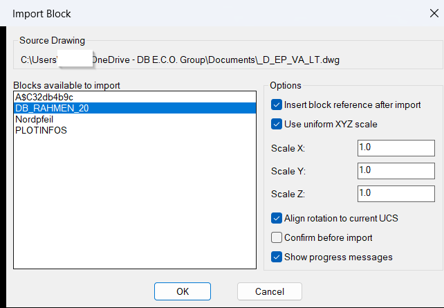
ImportBlock
- 🚀 Import blocks from external drawings – select a source
DWG,DWT, orDWSand copy a chosen block definition into the active AutoCAD or Civil 3D drawing. - 🧩 DCL block picker – display available importable block definitions in a practical dialog instead of requiring manual block table browsing.
- 🔍 Filter unsafe or unavailable definitions – skip layout blocks, xrefs, anonymous blocks, externally referenced names, and definitions already present in the current drawing.
- 📌 Optional immediate insertion – import only the block definition or insert a block reference immediately after import.
- 📐 Scale control – use uniform XYZ scale or separate
Scale X,Scale Y, andScale Zvalues for inserted block references. - 🧭 UCS rotation alignment – align inserted blocks to the current UCS when the Align rotation to current UCS option is enabled.
- 📝 Confirm before import – use an optional confirmation prompt before copying the selected block definition into the active drawing.
- 💾 Saved settings – remember source path, last block, scale options, toggles, and dialog position in
ImportBlock.cfg. - 🔄 ObjectDBX workflow – read external drawing block definitions efficiently without forcing the user to open the source drawing in the editor.
- 🟢 Non-destructive source handling – the selected source drawing is read for block definitions while the source file itself is not modified.
- 🚀 Import blocks from external drawings – select a source
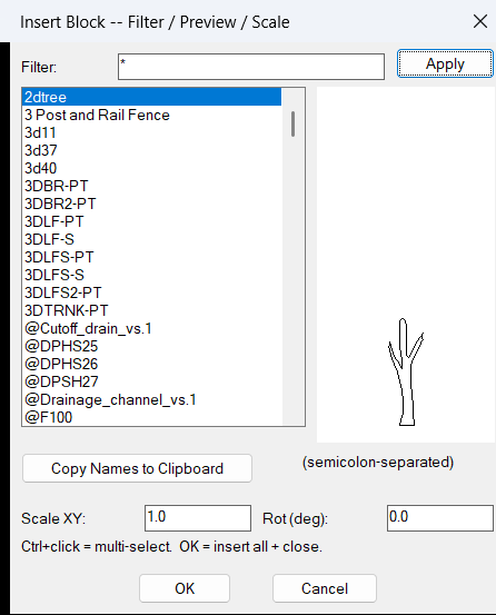
InsertBlockFilterScale
- 🚀 Open a block insertion browser – launches a practical DCL interface for browsing block definitions in the active AutoCAD or Civil 3D drawing.
- 🔍 Filter block names quickly – supports text filters and wildcard search patterns to find the required block without scrolling through long block tables.
- 🧩 Preview block geometry – shows a simplified CAD-style preview of the selected block definition inside the dialog.
- 🔢 Multi-select block insertion – allows several block names to be selected and inserted in one command session.
- 📐 Scale and rotate inserted blocks – applies the user-entered XY scale and rotation angle during insertion.
- 📍 Pick insertion points interactively – prompts for a drawing point for each selected block and places each block exactly from the user workflow.
- 🧭 Respect current UCS orientation – converts the picked UCS point to WCS and adds UCS rotation to the inserted block rotation.
- 📋 Copy selected block names – copies selected block names to the Windows clipboard as a semicolon-separated list.
- 🔐 Remember user preferences – stores filter text, scale, rotation, selected block names, and dialog position for later sessions.
- 🧰 Print debug diagnostics – uses
IBB-DEBUGto display internal log messages for troubleshooting.
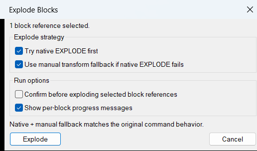
ExplodeBlocks
- 🚀 Explode hard-to-edit blocks – converts selected block references into editable AutoCAD geometry.
- 🔒 Bypass blocked explode settings – temporarily enables the block definition
Explodableproperty and restores it after the explode attempt. - 📐 Handle non-uniform block scale – uses a manual transformation fallback when AutoCAD native explode cannot handle the selected block reference.
- 🧩 Process multiple blocks – supports batch selection and processes every selected
INSERTreference in one run. - 🔄 Use native explode first – relies on AutoCAD
._EXPLODEwhen possible for normal block reference behavior. - 🧠 Fallback to copied block definition geometry – copies definition entities and transforms them into drawing coordinates if native explode fails.
- 🧹 Delete original block references – removes the original block after the manual explode replacement is created.
- 🔍 Report success and failure counts – gives the user clear command-line feedback after the batch operation.
- 📌 Support nested block workflows – can expose nested block references one level at a time depending on the contents of the block definition.
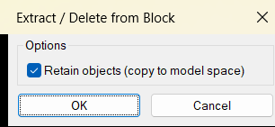
DeleteObjectFromBlock
- 🚀 Extract nested block objects – copies a picked object from inside a block into model space and removes it from the block definition.
- 🔴 Delete nested block objects – removes unwanted internal block geometry without creating a copy in model space.
- 🧠 Shared command workflow –
ExtractFromBlockandDeleteObjectFromBlockuse the same dialog and pick loop for consistent behavior. - 📌 Retain objects toggle – lets the user choose between copy and remove or delete only before picking nested geometry.
- 🔍 Interactive pick loop – repeatedly asks the user to pick nested objects and ends cleanly when the user presses Enter.
- 📐 Accurate object placement – applies the nested transformation matrix so extracted geometry is placed correctly in model space.
- 🏷️ Layer preservation and cleanup – keeps extracted objects on a clean local layer and can copy color, linetype, and lineweight settings.
- 🔒 Xref and layout protection – avoids editing xref blocks and layout definitions, reducing the risk of invalid database edits.
- 🧹 Block definition cleanup – removes unnecessary internal objects from reusable blocks, helping reduce DWG clutter.
- 🧰 Temporary DCL interface – generates and deletes the DCL file automatically from the Windows TEMP folder.
- 🔄 Undo-aware editing – wraps the pick session in an AutoCAD undo mark for easier rollback.
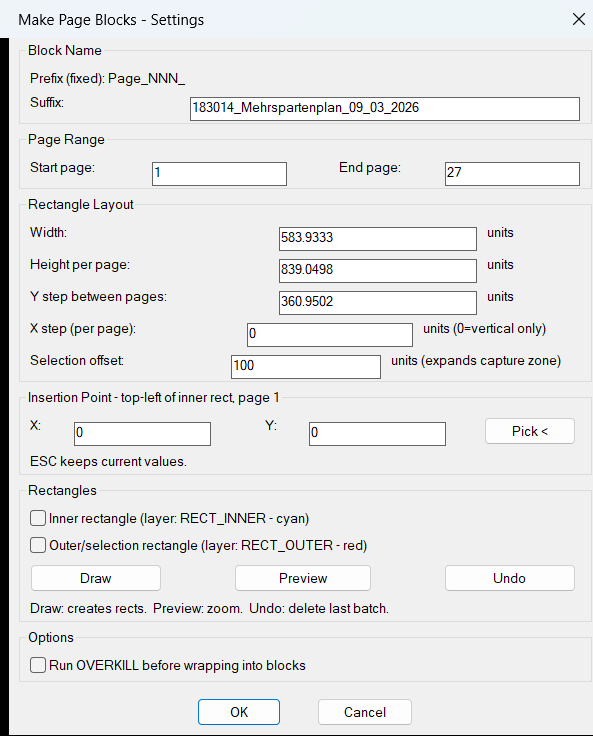
CreateMultipleRectangleBlocks
- 🚀 Create page block definitions – converts repeated drawing page zones into AutoCAD block references for cleaner DWG organization.
- 📐 Draw inner and outer rectangles – creates visual page frames and selection zones on dedicated layers
RECT_INNERandRECT_OUTER. - 🔢 Batch page range processing – generates multiple pages from a start and end number, making it suitable for large drawing sets and repeated sheet layouts.
- 🏷️ Automatic block naming – creates predictable block names using
Page_NNN_suffixso exported or managed page blocks are easy to identify. - 📌 Pick insertion point – allows the user to select the top-left origin of page 1 directly from the drawing.
- 🔍 Preview rectangle layout – zooms to the calculated rectangle area so the user can verify the layout before final block creation.
- ↩️ Undo last rectangle batch – uses AutoCAD undo marks to remove the last drawn preview rectangles quickly.
- 🧹 Optional OVERKILL cleanup – can remove duplicate or overlapping geometry before wrapping page entities into blocks.
- 🧩 Wrap entities into blocks – copies matching drawing entities into each block definition and replaces the source content with a block insert.
- 📊 Command-line progress report – prints collection counts, skipped blocks, empty blocks, and created block results for review and quality control.
- 🎯 Civil 3D production support – helps organize AutoCAD and Civil 3D drawing content into reusable page-based block references for drafting, cleanup, and deliverable preparation.
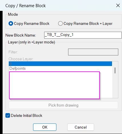
CopyBlock_vs.01
- 🚀 Copy and rename a block reference – creates an independent block definition from the selected block reference and assigns the copied reference to the new definition.
- 🏷️ Automatic block name proposal – generates a safe default block name based on the original effective name and an available numeric suffix.
- 🧩 Two workflow modes – supports simple
Copy Rename Blockand extendedCopy Rename Block + Layerprocessing. - 🎨 Layer assignment mode – lets the user choose a layer from the drawing and place the copied block reference on that layer.
- 🔍 Layer filter list – provides a searchable layer list in the DCL dialog so users can quickly find the required CAD layer.
- 📌 Pick layer from drawing – allows layer selection by clicking an existing object, making layer matching faster and less error-prone.
- 🧹 ByLayer block content cleanup – optionally updates entities inside the newly created block definition to the target layer and resets color, linetype, and lineweight to ByLayer behavior.
- 🔴 Delete initial block option – removes the originally selected block reference after the copy is created when the default toggle is left enabled.
- 🔒 Block and layer validation – rejects non-block entities, avoids locked-layer block edits, validates new block names, and prevents duplicate block table names.
- 📐 Preserves copied reference geometry – uses
vla-Copyso the copied block reference keeps the placement, rotation, scale, and other reference-level data from the original. - 🧰 ObjectDBX block definition workflow – uses a temporary ObjectDBX database to rename a copied block definition before importing it back into the active DWG.
- 🟢 DCL-based interface – gives the user a compact dialog instead of requiring manual command-line block table editing.
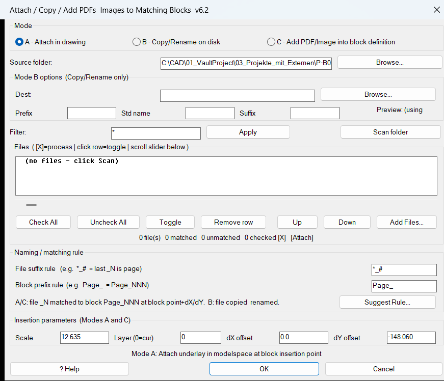
AttachImagesToBlocks
- 🚀 Attach PDFs and images to blocks – places matched files in model space at the corresponding block insertion point with user-defined scale and offsets.
- 📤 Copy and rename PDFs by block name – creates organized PDF copies on disk using matched block names or custom naming patterns.
- 🧩 Add underlays into block definitions – embeds the attached PDF or image into the matched block definition instead of leaving it only in model space.
- 🔍 Scan folders for supported file types – reads PDF, JPG, JPEG, PNG, TIF, TIFF, and BMP files from a selected folder.
- 🏷️ Match files to blocks by page number – pairs file names and block names using editable rules such as
*_#,##_*, andPage_. - 🧠 Suggest matching rules automatically – analyzes real file names and block names, then proposes rule combinations with the highest match count.
- 📌 Filter and manually add files – narrows scanned files with a wildcard filter and allows additional files to be added manually through the dialog.
- 🔢 Control selection rows – supports select all, select none, toggle row, remove row, move row up, move row down, and horizontal scrolling for long names.
- 📐 Apply offset and scale settings – uses configured
dX,dY, and scale values when attaching files at block insertion points. - 🧹 Use a target layer – creates or activates a layer before attachment for cleaner CAD underlay organization.
- 📝 Preview rename results – shows how the output name pattern will look before copying files.
- 📘 Display built-in rule help – explains file suffix rules, block prefix rules, and live examples from the current DWG and folder scan.
- 🔒 Group operations into undo marks – attach and embed actions are wrapped in AutoCAD undo workflows so the user can reverse the batch operation.
- 🔐 Save reusable settings – stores the last used configuration in the drawing folder for repeated production use.
Convert3DFaceToPolyline
- 🚀 Convert 3D faces to polylines – transforms selected face entities into practical editable AutoCAD polyline outlines.
- 🔍 Select multiple 3D faces – processes a selection set so several objects can be converted in one command run.
- 📐 Extract face vertices – reads the four corner points from each selected 3D face using AutoLISP entity data.
- 🧩 Create closed polyline boundaries – builds closed shapes that visually represent the original 3D face perimeter.
- 🧠 Skip invalid geometry – reports 3D faces that do not contain the expected vertex information instead of stopping the whole workflow.
- 🧹 Support DWG cleanup – helps convert face-based legacy geometry into easier-to-edit CAD linework.
- 📌 Improve Civil 3D preparation – provides cleaner polyline geometry for review, drafting, surface-related preparation, and production drawing coordination.
- 📘 Provide ribbon help content – the XAML tooltip explains the command syntax, command behavior, important functions, and usage steps for users.
3DF_to_3DPoly
- 🚀 Convert 3DFACE to 3D Polyline – quickly transforms face geometry into editable closed 3D polyline objects.
- 📐 Preserve vertex elevations – keeps the original Z values from the selected 3DFACE vertices.
- 🔍 Select multiple faces – processes an AutoCAD selection set so several 3DFACE entities can be converted in one command run.
- 🧩 Create closed boundaries – uses the four face vertices and closes the generated 3D polyline automatically.
- 🧠 Use direct DXF data – reads entity vertex data from
entgetinstead of relying on manual point picking. - 🔒 Restore drafting settings – returns
CMDECHOandOSMODEafter processing or after an error. - 🧹 Improve drawing cleanup – helps replace legacy 3DFACE objects with more practical 3D polyline geometry for CAD editing.
- 📘 Support Civil 3D production workflows – useful before terrain cleanup, feature interpretation, surface boundary preparation, 3D drafting, and DWG conversion tasks.
BookmarkEntities
- 🚀 Open a bookmark manager dialog – run
BMEntityPosto manage saved entity positions from a DCL interface. - 📌 Pick objects from the drawing – select text, lines, polylines, circles, splines, and blocks with
ssget. - 📐 Store entity extents – save lower-left and upper-right coordinate windows for future zoom operations.
- 🔍 Zoom to bookmarked positions – return instantly to saved DWG locations using padded
vla-ZoomWindownavigation. - 🔐 Refresh zoom by entity handle – use
handentto re-check the original object before zooming when possible. - 📝 Add and update remarks – attach practical review notes, coordination comments, or QA remarks to each bookmarked object.
- 📊 Use synchronized list boxes – inspect element labels, coordinates, color data, and remarks in aligned DCL lists.
- 🏷️ Filter bookmarks by group – show All, Text, Lines, Polylines, Circles, Splines, Blocks, or Other object categories.
- 🧩 Duplicate bookmark rows – clone a selected bookmark entry immediately after the original item.
- 🔴 Delete selected bookmarks – remove unwanted saved positions from the in-memory bookmark list.
- 🧹 Clear all bookmarks – reset the active bookmark list and refresh the DCL interface.
- 📤 Save bookmark lists – write the current list to
[DWG base name]_BMEntityPos.lstin the drawing folder. - 📘 Load default bookmark lists – reload saved bookmark data from the active drawing folder.
- 🧰 Import external bookmark lists – replace the current in-memory list with a selected
.lstfile. - 🎨 Capture color metadata – read true color
DXF 420or color indexDXF 62, including ByLayer and ByBlock cases.
- 🚀 Open a bookmark manager dialog – run
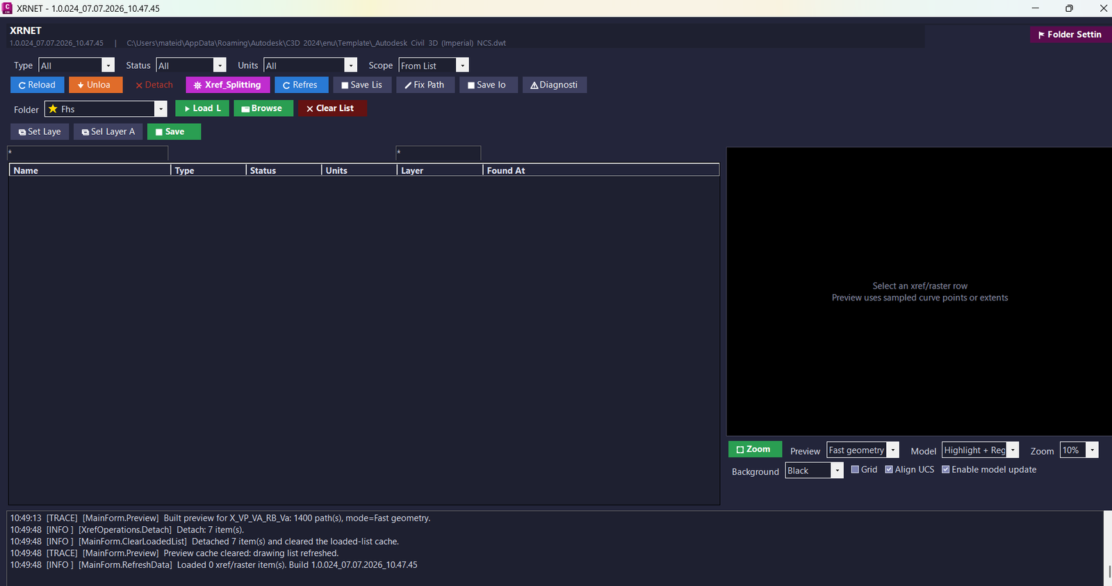
XrNet
- 🚀 Open XRNET xref manager – run a modeless control panel for AutoCAD and Civil 3D external reference management.
- 🔍 Scan active DWG references – list DWG xrefs and raster images with name, type, status, units, layer, and path.
- 🔄 Reload selected references – update selected references to use the latest source files.
- 🟧 Unload selected references – unload xrefs or hide raster images while preserving the reference structure.
- 🔴 Detach selected references – remove unwanted xrefs or raster references from the active drawing.
- 📌 Attach missing list entries – apply saved xref list records and attach missing DWG files.
- 🧩 Convert xref type – change references between Overlay and Attached where supported.
- 🧹 Set organized xref layers – move references onto clean generated xref layers for better drawing management.
- 📊 Load and save xref lists – read and write reusable TXT reference lists for repeatable CAD coordination workflows.
- 📤 Export CSV reports – export selected xref splitter rows for review, checking, and project coordination.
- 🧠 Fix and validate paths – detect missing paths, blank paths, and path problems before they become production issues.
- 📐 Preview selected references – display selected DWG geometry before applying changes.
- 🔢 Zoom, pan, fit, grid, and UCS options – improve visual inspection with CAD-style navigation controls.
- 📝 Edit xref splitter rows – add, delete, reorder, validate, edit, and apply list entries.
- 🏷️ Generate layers and abbreviations – create organized layer values and short names for consistent xref naming.
- 📘 Manage predefined folders – store project folder shortcuts for faster reference workflows.
- 🔒 Use dry-run mode – check apply actions before modifying the active drawing.
- 🧰 Save logs and diagnostics – export troubleshooting information and operation logs.
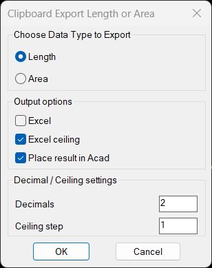
TotalLengthAreaDetailed
🚀 DCL dialog workflow for choosing Length or Area.
📏 Detailed total length calculation for lines, polylines, arcs, circles, ellipses, splines, mlines, regions, and mpolygons.
📐 Detailed total area calculation for closed polylines, circles, ellipses, regions, hatches, and mpolygons.
📋 Clipboard export as additive expression, Excel formula, or CEILING formula.
🧮 Optional Profile_002 profile conversion for profile-width based quantity extraction.
📝 Optional MTEXT placement in AutoCAD using UCS to WCS transformation.
🔗 Dynamic AutoCAD field support for object properties such as Length, ArcLength, Circumference, Perimeter, and Area where available.
🏷️ Version 02 selected-layer behavior for MTEXT placement and layer-labeled results.
💾 Persistent user settings through CTC_* environment variables.
🎯 Decimal precision and ceiling step controls.
🔐 Type-based object filtering with safe fallbacks for unsupported field properties.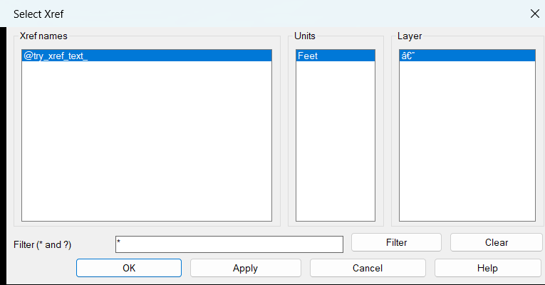
ZoomXref
• Scans the active drawing block table for Xref block definitions.
• Displays Xref names in a generated DCL dialog.
• Shows readable unit names such as Meters, Millimeters, Feet, Inches, and Unitless.
• Summarizes the layer used by model-space Xref inserts, including Multiple when inserts use more than one layer.
• Supports live wildcard filtering with * and ?.
• Keeps name, units, and layer list selections synchronized.
• Uses Apply to zoom without closing the dialog.
• Uses OK to zoom and close the dialog.
• Computes the combined lower-left and upper-right bounding box of selected Xref references.
• Uses pure ActiveX ZoomWindow rather than command-line ZOOM or vl-cmdf.
• Provides a SELECTXREF alias that launches the same workflow.
• Creates the DCL interface temporarily and deletes the temporary DCL file after use.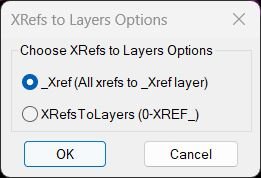
XRefs2Layers
🔗 XREF detection — scans AutoCAD Blocks collection for definitions where IsXRef is true.
🧹 TBLOCK exclusion — skips XREF names matching *TBLOCK* to avoid processing title-block style references.
🪟 DCL option dialog — provides a simple radio-button interface for choosing the layer organization mode.
📂 Per-XREF layer mode — moves XREF inserts to uppercase layers named with the 0-XREF_ prefix.
🟦 Shared layer mode — moves all XREF inserts to one standard _XREF layer.
🧱 Layer auto-create — creates missing destination layers automatically.
🔐 Locked-layer handling — temporarily unlocks the current layer when required so the XREF can be moved.
↩️ Undo mark support — wraps processing in an undo mark for safer drawing edits.
📊 Move report — displays a summary alert showing counts by target layer.
⚙️ Session memory — remembers the last selected radio option during the active AutoCAD session.
🚫 Zero-XREF warning — alerts the user when no XREFs are found in the drawing.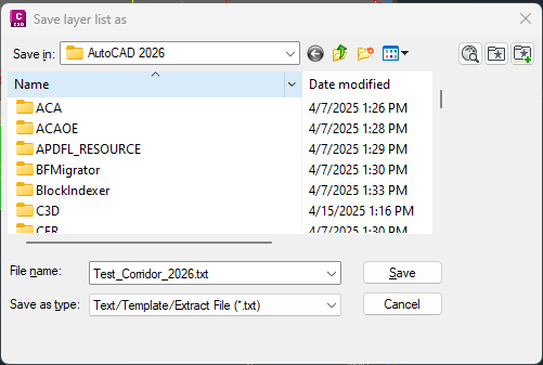
LayerList
- 📊 Export active drawing layers — Creates a text report of all layers in the current AutoCAD or Civil 3D drawing.
- 🔍 Audit layer visibility — Reports whether each layer is On or Off for faster drawing diagnostics.
- 🧊 Review freeze states — Shows whether each layer is Frozen or Thawed, including viewport default freeze information.
- 🔒 Check locked layers — Identifies locked and unlocked layers for CAD management and editing control.
- 🎨 Document layer appearance — Exports color, linetype, lineweight, and plot style values for standards comparison.
- 🖨️ Verify plotting behavior — Reports whether layers are plottable or not plottable, helping solve plotting and publishing problems.
- 📤 Excel-friendly output — Writes a text file that can be imported into Excel for filtering, sorting, documentation, and QA review.
- 🧹 Non-destructive CAD audit — Reads drawing layer properties without changing entities, layer definitions, styles, blocks, xrefs, or Civil 3D objects.
ConvertPolylineAndText2Mleader
[‘🚀 Runs from the AutoCAD command line with P2L.’, ‘📐 Selects supported polyline objects using ssget with the *POLYLINE filter.’, ‘🔄 Converts each selected polyline path into an AutoCAD LEADER sequence.’, ‘🧩 Reads polyline vertices using vlax-curve-getEndParam and vlax-curve-getPointAtParam.’, ‘🟢 Handles closed polylines by avoiding the duplicated closing vertex during leader creation.’, ‘🎨 Applies MATCHPROP so the generated leader inherits visual properties from the original polyline.’, ‘🧹 Deletes the source polyline after a successful leader conversion to keep the drawing clean.’, ‘📌 Processes multiple selected polylines in one run.’, ‘🔒 Uses a locked-selection mode in ssget to avoid editing locked objects.’]
ConvertLeaderAndText2Mleader
🧰 Select an existing MULTILEADER to reuse its style, scale, width, and visual behavior, or skip the step to use the current MLEADER style.
🔁 Convert one old LEADER and one MTEXT object into a new MLEADER object with a clean AutoCAD annotation workflow.
📝 Convert MTEXT content using Title case, Lower case, Upper case, Sentence case, Toggle case, or Keep case options.
🧹 Keep MTEXT formatting or remove MTEXT formatting codes with a Lee Mac unformat routine.
📐 Rebuild leader geometry from the original leader points, supporting straight leaders, dog-legged leaders, and simplified multi-vertex leaders.
🎯 Preserve MTEXT rotation and reuse text width when appropriate for cleaner MLEADER placement.
📌 Move the new MLEADER to the original MTEXT layer when no reference MLEADER is selected.
🔒 Use undo marks, error handling, CMDECHO restoration, OSMODE restoration, and safe selection prompts.
🧠 Support annotative object checks through ActiveX and dictionary inspection helpers.
⚙️ Use helper routines for selection filtering, rounded point coordinates, string substitution, text unformatting, and annotative detection.AddVertex2Mleader
• 🎯 Selects one AutoCAD MULTILEADER entity from the drawing.
• 📌 Prompts the user to pick the new leader vertex point interactively.
• 🧠 Reads the current leader line vertices using getleaderlinevertices.
• 🔄 Inserts the picked point into the leader vertex sequence instead of recreating the whole MLeader manually.
• 📐 Uses distance-based logic to place the new point near the closest existing leader vertex position.
• 🧩 Updates the first leader line using setleaderlinevertices.
• 🧹 Leaves unsupported selections unchanged when the selected object is not a MULTILEADER.
• ⚙️ Uses Visual LISP ActiveX automation with vlax-ename->vla-object and vlax-invoke.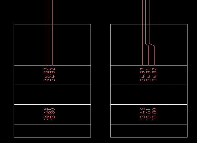
FixLineTextOverlap
🚀 Selects vertical LINE entities and creates clean crank-style LWPOLYLINE step-outs.
📏 Computes a practical default spacing from 1.25 times the current AutoCAD TEXTSIZE.
🎯 Lets the user pick a crank point that defines the Y level and rail position for spacing.
🔄 Uses shared spacing and rail memory so Text_Overlap can reuse the last Line_Overlap settings.
🧩 Groups TEXT and MTEXT by Y row to avoid mixing annotations from different horizontal bands.
📌 Splits text into left and right sides of the rail, anchors the nearest item, and steps the rest outward.
📝 Supports both TEXT and MTEXT with proper insertion point handling.
🔧 Respects TEXT justification by editing DXF point code 10 for left-justified text and code 11 for right-justified text when needed.
🌐 Uses trans to move between OCS, UCS, and WCS safely during text edits.
🧱 Preserves the source layer for created crank polylines.
↩️ Wraps edits in an AutoCAD UNDO group for fast rollback.
⚠️ Reports empty selections or unsupported cases instead of silently failing.CopyPaste2BasePoint
📋 Copy selected objects using AutoCAD COPYBASE with base point 0,0,0.
📌 Paste clipboard geometry using AutoCAD PASTECLIP at insertion point 0,0,0.
🧭 Supports origin-based CAD transfer workflows between drawings.
🔒 Temporarily disables OSMODE to prevent object snap interference during copy and paste operations.
🧊 Temporarily disables 3DOSMODE when the variable exists, improving reliability in 3D snap environments.
🏗️ Handles AECBOSMODE when available, making the routine more compatible with AutoCAD MEP and AEC-based installations.
🔇 Temporarily suppresses CMDECHO for a cleaner command-line workflow.
↩️ Wraps operations in AutoCAD undo marks using ActiveX document methods.
✅ Restores previous drafting settings after the command completes.CopyMove2MidPoint
✅ Select multiple AutoCAD drawing objects for midpoint-based relocation.
📐 Define a source midpoint using two picked reference points.
🎯 Define a destination midpoint using two picked reference points.
🔄 Move selected entities with MMid2.
📋 Copy selected entities with CMid2.
🌐 Respect the active UCS by transforming base point and vector data to WCS.
🔒 Skip objects located on locked layers.
🧰 Use a single shared engine for move and copy behavior.CookieCutter2
– Runs the primary CookieCutter2 command with the CC shortcut.
– Accepts a circle or closed polyline, ellipse, or spline as the trimming edge.
– Rejects non-closed, self-intersecting, and unsupported boundary objects.
– Lets the user pick whether the inside or outside side of the boundary should be processed.
– Can erase all objects on visible layers inside or outside the selected boundary.
– Behaves like EXTRIM when the erase-all option is not selected.
– Explodes intersecting blocks and recursively processes nested blocks.
– Converts exploded block attributes into text while preserving key properties.
– Explodes regions and non-solid hatches that intersect the trimming boundary.
– Offers to convert intersecting solid hatches into ANSI31 lines before trimming.
– Ignores true external references and can process bound block content when it is explodable.
– Skips annotation and unsupported entities such as text, mtext, leaders, dimensions, mleaders, tables, solids, traces, and remaining solid hatches.
– Temporarily unlocks locked non-xref layers and relocks them when the command ends.
– Uses an offset boundary and IntersectWith calculations to determine reliable trim locations.
– Sorts multiple intersection points to improve repeated trimming behavior.
– Restores AutoCAD system variables, object visibility, layer locks, and the original view after completion or error.
– Wraps the operation in an AutoCAD undo mark.
– Includes CookieCutter2Multi and CC2M for keeping objects inside any of several closed boundaries by erasing objects outside their combined areas.
CenterAreaCentroid
✅ Dialog-based choice between Center Area and Centroid.
✅ Session memory for the last selected option using *CAC-last-option*.
✅ Temporary DCL creation with vl-filename-mktemp and load_dialog.
✅ Most-inner-point calculation for closed AcDbPolyline and planar closed AcDbSpline objects.
✅ AutoCAD POINT creation at the calculated inner point, using color index 3.
✅ Centroid extraction from a selected polyline converted to REGION.
✅ TEXT insertion at the centroid point with middle-center justification.
✅ Visual LISP ActiveX usage through vlax, vla, and curve functions.
✅ Lightweight command workflow for area labeling, centroid checking, and closed-boundary drafting support.TotalLengthPolyline
📏 Calculates total length from a user-selected set of AutoCAD objects.
🧱 Supports LINE, ARC, CIRCLE, SPLINE, POLYLINE, LWPOLYLINE, and ELLIPSE entities.
📐 Uses direct geometric distance calculation for LINE objects.
🟠 Computes ARC length from radius and angular span.
🔄 Uses AutoCAD AREA object mode to retrieve perimeter values for circles, splines, polylines, lightweight polylines, and ellipses.
➕ Adds every valid entity contribution into one final total.
📢 Displays the result in an AutoCAD alert window.
🧰 Works as a lightweight command-line utility without a DCL dialog or external files.TotalLengthAll
🚀 ELEN command for fast total-length calculation.
📏 Calculates total length for selected AutoCAD curve entities.
📐 Supports lines, polylines, 3D polylines, circles, arcs, ellipses, and splines.
🔍 Works with implied selection or manual entity selection.
🧹 Filters unsupported object types and reports skipped items.
📊 Prints entity count and total length in current drawing units.
🧰 Non-destructive workflow that does not modify drawing geometry.
⚙️ Compact AutoLISP routine suitable for quick CAD production checks.TLength
📏 Calculates total selected length from multiple AutoCAD object types.
📐 Uses vla-get-length for LINE, 3D POLYLINE, and POLYLINE objects.
🧭 Uses vla-get-arclength for ARC objects.
⭕ Uses vla-get-circumference for CIRCLE objects.
🌀 Uses vlax-curve-getdistatparam for SPLINE and ELLIPSE objects.
🧱 Calculates MLINE length from coordinate segment distances.
🟦 Uses vla-get-perimeter for REGION and MPOLYGON objects.
🔢 Formats the final result with four decimal places using rtos.
📋 Copies the final numeric value directly to the clipboard.
🖥️ Prints a single-object or multi-object total length message in the AutoCAD command line.
🧹 Cleans up the temporary AutoCAD selection set after calculation.SumLengthField
📏 Live length summation from selected linear objects.
🟦 Area summation from closed or area-capable objects.
🔢 Unit conversion command variants for mm to m and mm² to m² workflows.
📌 Output to new MText by picking a point in the drawing.
📊 Output directly into AutoCAD table cells.
🏷️ Output into Text, MText, Attributes, Attributed Blocks, and MLeaders.
🧩 Attribute selector dialog for blocks or MLeaders with multiple editable attributes.
🔄 FIELD expression generation using ObjectID references, AcObjProp, and AcExpr.
🧹 Existing field content is cleared before the new field is written.
🔐 Safe undo handling and locked-layer checks.PolylineArea
🚀 Launches from the AutoCAD command line with POLYAREA.
📐 Selects all supported polyline entities using the *POLYLINE object filter.
🧮 Calculates the total area of multiple selected polyline objects.
📏 Supports metric, unitless, and imperial display logic.
🟧 For imperial dimension settings, reports square inches and square feet.
📋 Copies the clean numeric result to the Windows clipboard automatically.
📊 Shows the full total area result in an AutoCAD alert dialog.
🧹 Releases the clipboard COM object after use.
⚠️ Displays a clear warning when no polylines are selected.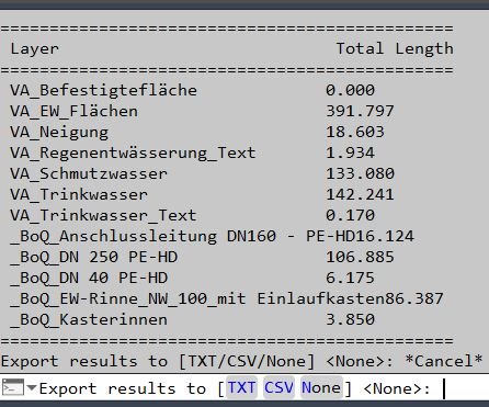
PLLengthByLayer
✅ Main functionalities:
– 🔍 Scans the full drawing for LWPOLYLINE objects with ssget “_X”.
– 🏷️ Reads the layer of each lightweight polyline.
– 📏 Calculates polyline length with vla-get-length.
– 📊 Groups and totals lengths by layer.
– 🔤 Sorts layer names alphabetically for the printed report.
– 🧾 Prints a command-line table with layer name and total length.
– 📤 Offers TXT, CSV, or no export after the summary.
– 💾 Writes exported reports to the current DWG folder.
– 🔐 Uses unique filenames to avoid overwriting previous exports.
– 🧹 Closes file handles safely through the local error handler.Exp_Imp_NamedViews
🚀 Launches a dedicated Named Views import and export dialog with the ExpImpNVU command.
📤 Exports all named AutoCAD VIEW definitions from the active drawing to a TXT file.
🎨 Exports linked VISUALSTYLE definitions once when a Named View references a visual style.
📥 Imports saved VIEW and VISUALSTYLE records back into the active drawing.
📁 Offers predefined project folders for Named_Views locations such as Beu, La, Npl, and Bis.
🧭 Uses the drawing name as the suggested TXT filename for fast project based exports and imports.
💾 Persists the last folder through the Windows registry path HKEY_CURRENT_USER\Software\JTBWorld\viewsIO.
🖥️ Provides helper buttons for opening the fixed LISP folder in Explorer and opening the LISP file in Notepad++.
🔄 Includes a reload helper for quickly reloading the fixed Exp_Imp_NamedViews LISP file during development.
📋 Includes a help dialog with copy selected, copy all, copy path, and Unicode toggle actions.
🧩 Supports GUI commands and command-line variants for scripted or manual workflows.
🛡️ Cleans handle, owner, and visual style link DXF codes during export so imported entities can be recreated safely.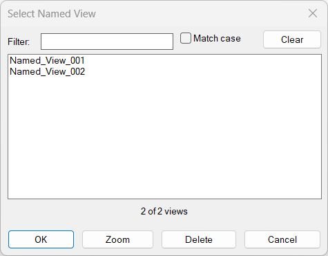
NamedViewList
🔍 Live filter box for narrowing Named View names in real time.
🔤 Match case toggle for case-sensitive or case-insensitive filtering.
📋 Multi-select list box for selecting one or more Named Views.
🧭 Zoom button applies the first selected view while the dialog stays open.
🗑️ Delete button removes selected views and refreshes the dialog without closing it.
📝 Double-click rename workflow with duplicate-name validation.
📊 Count label shows filtered results against the total number of views.
🔄 Clear filter button resets the search field and reloads all views.
✅ OK restores all selected views using the AutoCAD VIEW restore operation.
🧹 Error and cancellation cleanup unloads the temporary DCL and deletes the temporary dialog file.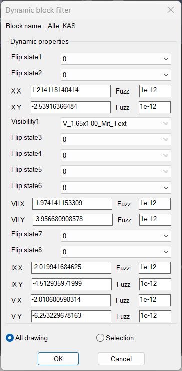
DynamicBlockFilter
- 🔍 Select matching dynamic blocks – automatically finds block references with the same effective dynamic block name and matching dynamic property values.
- 🧩 Filter by visibility, lookup, distance, angle, flip, stretch, and custom parameters – supports common AutoCAD dynamic block property workflows.
- 📊 DCL-based property selection – shows a compact AutoCAD dialog generated at runtime from the selected block properties.
- ⭐ Use wildcard all values – empty fields and
*allow broad matching without requiring every property to be specified. - 📐 Use fuzz tolerance for numeric values – improves matching for dynamic block distances, rotations, and calculated values affected by precision.
- 🟢 Filter the whole drawing – searches all block references in the active DWG for matching dynamic block configurations.
- 🟧 Filter only a manual selection – limits the search to selected objects when the user wants controlled local filtering.
- 🧰 Works inside other AutoCAD commands – the function can return a selection set during a command selection prompt, improving command chaining.
- 📌 Highlight results in model space – matched block references become the active AutoCAD selection set for immediate editing.
- 🧹 Useful for DWG cleanup and block auditing – quickly isolates specific dynamic block variants without manually inspecting every instance.
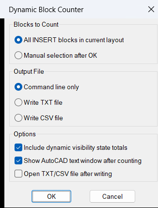
DynamicBlockCounter
- 🚀 Count all blocks in the current layout – press Enter at the selection prompt to count every detected
INSERTobject in the active model or layout context. - 🎯 Count selected blocks only – select specific block references when only part of the drawing should be audited.
- 🧩 Support dynamic blocks – resolves dynamic block effective names so reports use readable block names instead of anonymous internal names.
- 👁️ Visibility state reporting – counts each visibility state separately for dynamic blocks that use a visibility parameter.
- 📌 Include xref-style inserts – processes reference objects that appear as
INSERTentities in the current drawing layout. - 📊 Formatted AutoCAD command-line report – prints block names, visibility states, and counts in a structured table.
- 📤 Export block counts to TXT – creates a tab-delimited report for documentation, review, or quick sharing.
- 📤 Export block counts to CSV – creates a spreadsheet-friendly report for Excel, quantity checking, and project coordination.
- 🧠 Automatic unique filenames – avoids overwriting previous reports by adding a numeric suffix when an output file already exists.
- 🔒 Non-destructive drawing audit – reads block information and writes reports without editing, moving, deleting, or changing the drawing entities.
- 🚀 Count all blocks in the current layout – press Enter at the selection prompt to count every detected
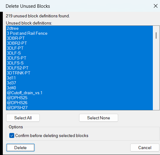
DelUnusedBlocks
- 🚀 Run a dedicated AutoCAD cleanup command — use
DelUnusedBlocksto start a focused unused block definition cleanup workflow. - 🔍 Scan unused block definitions — automatically checks the active DWG block table and finds block definitions that are not inserted in the drawing.
- 🔒 Skip protected block types — excludes xrefs, xref-dependent blocks, externally dependent blocks, layout blocks, and other non-deletable block records.
- 📋 Use a generated DCL dialog — displays unused block names in a practical multi-select list instead of forcing command-line-only cleanup.
- 🟢 Select all unused blocks — quickly marks every detected unused block definition for deletion.
- ⚪ Select none — clears the current selection when the user wants to manually choose only specific block names.
- ⚠️ Confirm before delete — optional confirmation helps prevent accidental cleanup actions in production DWG files.
- 🧹 Delete selected unused blocks — removes the selected unused definitions from the AutoCAD block table with ActiveX database operations.
- 💾 Remember user settings — saves dialog position, confirmation preference, and previous selected block names in
DelUnusedBlocks.cfg. - 📌 Restore previous selection — attempts to reselect previously chosen block names when they still exist in the next cleanup session.
- 📊 Command-line reporting — prints deleted block names and the total number of deleted unused block definitions.
- 🔐 Graceful cancel behavior — preserves settings and exits cleanly when the user cancels or closes the dialog.
- 🚀 Run a dedicated AutoCAD cleanup command — use
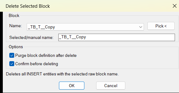
DelSelectBlock
- 🚀 Delete selected block name – removes every block reference in the active drawing that matches the chosen raw block name.
- 🔍 Scan all block references – lists available
INSERTblock names from the current DWG without manually searching the drawing. - 📌 Pick block from drawing – lets the user select one block reference and automatically fills the dialog with its block name.
- 📝 Manual block name input – allows direct typing of a raw block name for advanced cleanup workflows.
- 🧠 Recent block history – remembers the last used block names so repeated cleanup operations are faster.
- 🔒 Optional confirmation – shows the number of matching instances before deletion to reduce accidental drawing changes.
- 🧹 Optional block definition purge – attempts to remove the block definition after all matching references are deleted.
- 🎨 Persistent DCL position – saves and restores the dialog position for a smoother CAD production workflow.
- 📋 Configuration file support – stores options in
DelSelectBlock.cfgusing AutoCAD roaming, drawing, or temporary paths. - 🔐 Wildcard-safe selection – supports literal matching of special raw block names, including anonymous dynamic block names.
- 🧰 Command-line feedback – reports how many block instances were deleted and how many could not be removed.
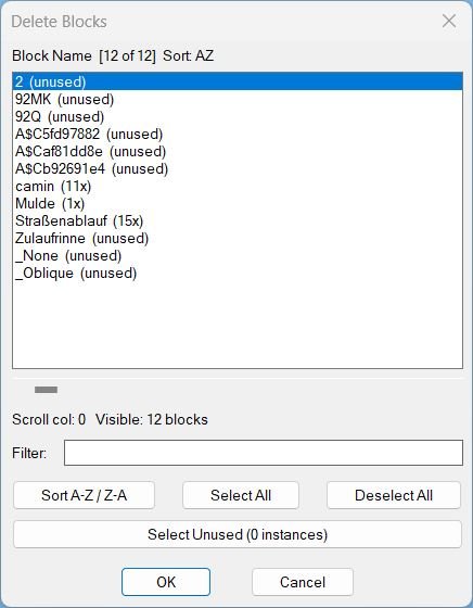
DeleteBlocks
- 🚀 Open block deletion manager – runs
DELBLOCKSto display a DCL list of deletable block candidates. - 🔢 Show block instance counts – displays how many references each block name has in the drawing database.
- 🔍 Filter block names – narrows the list by text so users can quickly find target block definitions.
- 🔄 Sort A-Z or Z-A – changes the block list order for faster navigation in drawings with many block definitions.
- 📌 Select multiple blocks – allows multi-select deletion from one dialog instead of running repeated command-line cleanup steps.
- 🧹 Select unused blocks – automatically selects zero-instance blocks for purge-style drawing cleanup.
- 🟧 Select all and deselect all – speeds up bulk block cleanup and review workflows.
- 📊 Horizontal scroll simulation – uses a DCL slider to inspect long block names that do not fit in the list box.
- 🔴 Nested block protection warning – warns when a selected block is used inside another block definition before proceeding.
- 🔒 Locked layer support – temporarily unlocks layers so matching block references can be deleted, then restores the layer lock state.
- 🧠 Persistent user settings – remembers the last filter, scroll position, sort direction, and dialog size between runs.
- 🧰 Temporary DCL creation – creates a unique dialog file per session and removes it after use.
- 🔴 Global block deletion – removes matching block references and attempts to delete the selected block definitions from the active DWG.
- 🚀 Open block deletion manager – runs
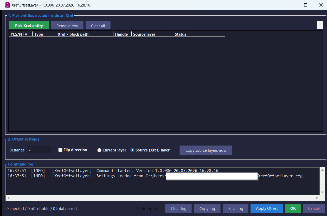
XrefOffsetLayer
- 🔍 Pick individual entities nested inside Xrefs using a dedicated modeless dialog.
- 📐 Offset supported curve objects such as lines, arcs, circles, ellipses, lightweight polylines, and splines.
- 🔄 Use Flip direction to offset to the opposite side without typing a negative distance.
- 🏷️ Choose between placing offsets on the current host layer or on a cloned source Xref layer.
- 📂 Run
XOFFSETCPLAYSto clone Xref-dependent layer definitions from the source drawing into the host drawing. - 🧩 Supports nested Xref containers by transforming created geometry through the full block reference path.
- 📊 Displays picked entities in a grid with apply status, entity type, handle, layer, block path, and readiness state.
- 📋 Copies the entity table to the clipboard as tab-separated data for Excel or Notepad review.
- ↩️ Provides Undo Apply for the last offset operation in the dialog session.
- 📝 Includes live log, copy log, save log, and clear log workflows for repeatable diagnostics.
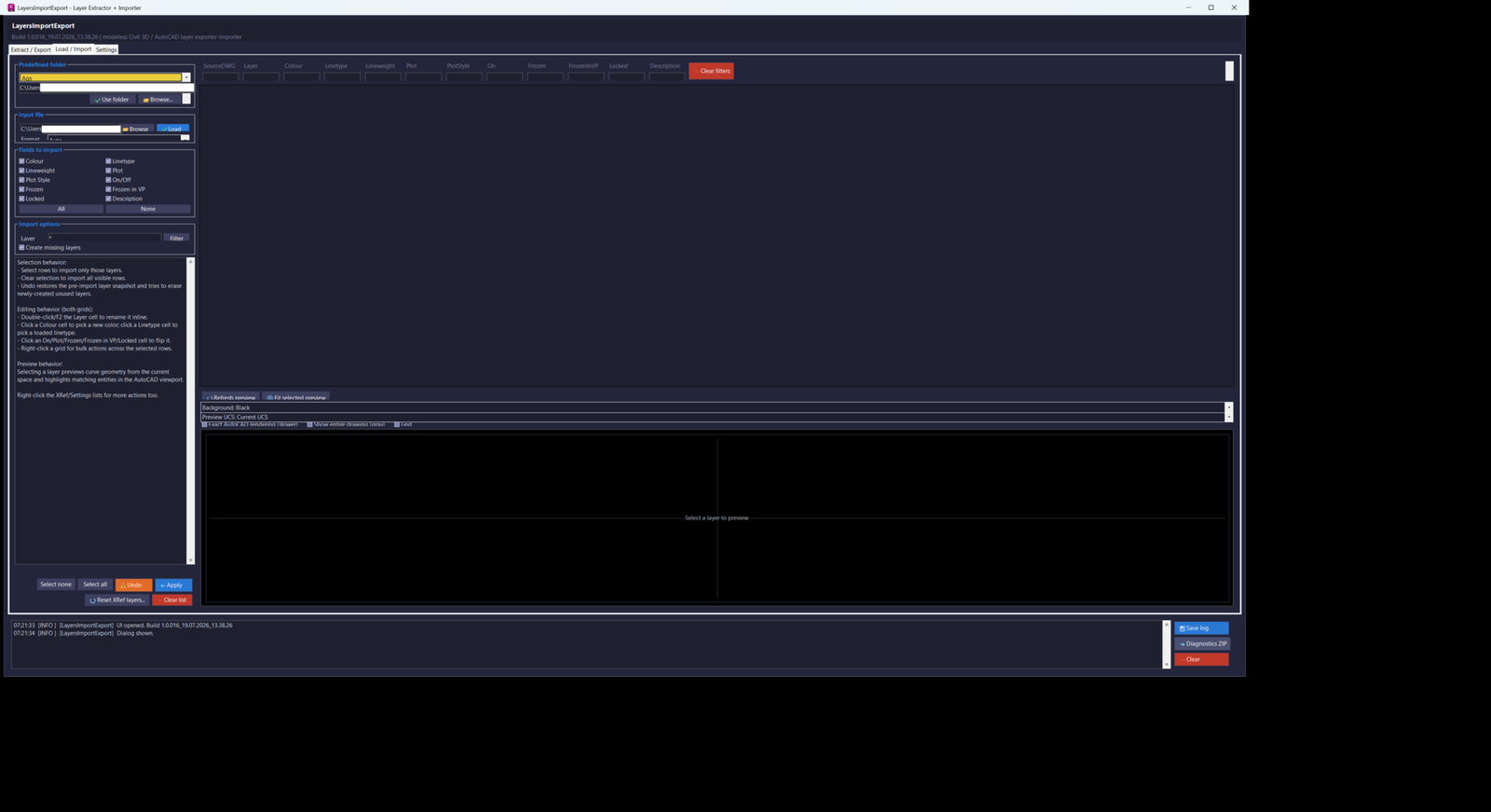
LayersImportExport
– Registers the collision-safe LAYERSIMPORTEXPORT_016 combined command.
– Registers LAYEREXPORT_016 to open the Extract / Export tab.
– Registers LAYERIMPORT_016 to open the Load / Import tab.
– Registers LAYERSETTINGS_016 to open the Settings tab.
– Uses a build-numbered assembly and command system for side-by-side NETLOAD testing.
– Targets AutoCAD and Civil 3D 2024 or later through .NET Framework 4.8.
– Opens one modeless and resizable Windows Forms interface.
– Extracts layer definitions from the active drawing.
– Extracts layers from all DWG files in a selected directory.
– Optionally scans DWG subfolders recursively.
– Runs directory extraction on a background thread with progress and cancellation.
– Reports DWG files that could not be read.
– Exports layer records as UTF-8 CSV.
– Exports layer records as XML.
– Imports layer records from CSV.
– Imports layer records from XML.
– Supports Layer, Colour, Linetype, Lineweight, Plot, PlotStyle, On, Frozen, FrozenInVP, Locked, and Description fields.
– Includes SourceDWG in directory-export records when required.
– Supports ACI colour values.
– Supports true-colour values stored as TC:R,G,B.
– Lets users choose which fields are included in Export.
– Lets users choose which fields are applied during Import.
– Creates missing layers when enabled.
– Updates existing layers when enabled.
– Reports created, updated, skipped, and failed layer counts.
– Shows Import Apply progress and supports cooperative cancellation.
– Captures a layer snapshot before live drawing changes.
– Restores the latest drawing-layer change through Undo.
– Applies selected edited Export-grid rows directly to existing layers in the current drawing.
– Confirms live drawing changes before Apply.
– Includes or excludes Xref-dependent layers during extraction.
– Restricts output to Xref layers only.
– Filters output by one or more selected Xref owners.
– Picks an Xref from a block reference, nested entity, or attribute-related selection in the viewport.
– Automatically checks the picked Xref and isolates its layer rows.
– Uses the picked Xref name as the export filename base.
– Displays the reason used to determine the next export filename.
– Recomputes timestamped output paths automatically unless the path is explicitly locked.
– Selects export folders from matched project names, chosen predefined folders, source folders, or fallback locations.
– Resets local Xref-layer overrides from the Xref source drawing.
– Opens the resolved Xref source DWG as a read-only side database.
– Confirms Xref reset operations and supports Undo.
– Lets users rename pending layer rows inline.
– Opens an AutoCAD-style ACI and true-colour picker from Colour cells.
– Lists loaded drawing linetypes for click-to-change editing.
– Lists standard AutoCAD lineweights for click-to-change editing.
– Toggles On, Plot, Frozen, Frozen in VP, and Locked states by clicking cells.
– Applies cell edits across multiple selected rows.
– Displays colour swatches for ACI and true-colour values.
– Displays boolean grid values as On or Off instead of raw numeric values.
– Provides per-column case-insensitive filters.
– Supports explicit asterisk and question-mark wildcard filters.
– Applies Export, Copy CSV, and Apply-to-drawing actions to the currently visible filtered rows.
– Provides right-click menus for preview, copying, selection, field editing, Xref actions, project folders, and logs.
– Copies selected grid rows as CSV to the Windows clipboard.
– Provides an interactive GDI+ preview with mouse-wheel zoom.
– Supports left, middle, or right-button preview panning.
– Fits preview geometry on double-click.
– Refreshes the preview and fits the selected layer.
– Debounces rapid grid-selection preview changes.
– Recurses through nested blocks and Xrefs for layer preview geometry.
– Caps recursive preview scans to protect responsiveness in large drawings.
– Shows selected layer geometry in its resolved colour.
– Optionally shows all other current-space geometry as gray context.
– Provides selectable black, white, and gray preview backgrounds.
– Provides WCS, Current UCS, and named-UCS preview orientations.
– Provides an optional preview grid.
– Provides optional Exact AutoCAD rendering through the AutoCAD GraphicsSystem.
– Re-enables Exact AutoCAD rendering in build 016.
– Logs GraphicsSystem initialization errors, rebuild errors, exception types, stack information, added entities, skipped entities, selected highlight, and context counts.
– Highlights matching top-level drawing objects through implied selection when possible.
– Manages a schema-versioned ProjectFolders.json database.
– Supports Add, Update, Rename, Duplicate, Delete, Top, Up, Down, and Bottom project-folder operations.
– Assigns separate default Export and Import folders.
– Highlights and automatically selects default project folders.
– Auto-selects a project folder from the active DWG filename when no saved or default choice applies.
– Opens configured project folders in Windows Explorer.
– Auto-saves project-folder changes.
– Reads legacy unversioned project-folder arrays.
– Backs up corrupted project-folder databases before reseeding defaults.
– Persists interface and workflow settings in LayersImportExport.cfg.
– Maintains a timestamped live application log.
– Copies log selections or the complete log.
– Saves logs under the LayersImportExport application-data folder.
– Creates a diagnostics ZIP for troubleshooting.
– Uses generated GDI+ button icons with no external image files.
– Uses DPI-aware sizing, anchoring, docking, and scrolling for smaller screens.
– Prevents Escape from accidentally closing the modeless dialog.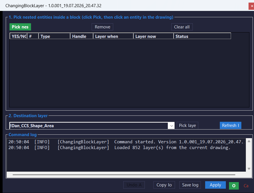
ChangeBlockLayer
– Registers the collision-safe CHANGEBLOCKLAYER_001 command.
– Registers CHANGEBLOCKLAYER and CNL as stable convenience aliases.
– Uses a modeless, resizable C# Windows Forms interface.
– Lets users click Pick nested entity repeatedly while the form remains open.
– Uses Editor.GetNestedEntity to retrieve the real ObjectId of the selected entity.
– Retrieves the complete chain of containing block-reference ObjectIds.
– Builds a FullSubentityPath by reversing the container chain and appending the nested entity.
– Highlights only the selected nested piece rather than the entire outer block reference.
– Accumulates multiple picked entities in a reviewable grid.
– Displays Apply, index, type, handle, original layer, current layer, and status columns.
– Checks newly selected modifiable rows by default.
– Detects whether any containing block definition is an external reference.
– Marks Xref-contained entities as INSIDE XREF (not modifiable).
– Disables and clears the Apply checkbox for Xref-contained rows.
– Loads all current drawing layer names from the LayerTable.
– Sorts destination layers alphabetically.
– Provides autocomplete in the destination-layer dropdown.
– Refreshes the destination-layer list from the current drawing.
– Lets users type a destination layer name and validates that it exists before Apply.
– Lets users pick a destination layer from a top-level entity.
– Lets users pick a destination layer from an entity nested inside a block.
– Removes an individual selected row and clears its viewport highlight.
– Clears all rows and removes all nested-subentity highlights.
– Shows checked, modifiable, and total-picked counts.
– Confirms the number of checked entities and destination layer before changing geometry.
– Changes only checked, modifiable entities.
– Changes the real entity Layer property inside a normal AutoCAD transaction.
– Regenerates the drawing after Apply so the new layer properties are visible.
– Updates row status to READY, APPLIED to the current layer, NOT FOUND, or INSIDE XREF.
– Keeps the modeless form open after Apply.
– Applies the same confirmed change and closes the form after OK.
– Warns when no destination layer is selected.
– Warns when no modifiable rows are checked.
– Allows OK to close without changes only after explicit confirmation.
– Stores the original layer of every successfully changed entity.
– Restores the latest Apply operation through Undo Apply while the dialog remains open.
– Enables Undo Apply only when a restorable Apply record exists.
– Maintains a timestamped live command log.
– Copies the command log to the Windows clipboard.
– Saves a diagnostic log with version information and picked nested-entity details.
– Uses build-numbered assembly and command generation for side-by-side test builds.
– Targets .NET Framework 4.8 and x64 AutoCAD or Civil 3D 2024 environments.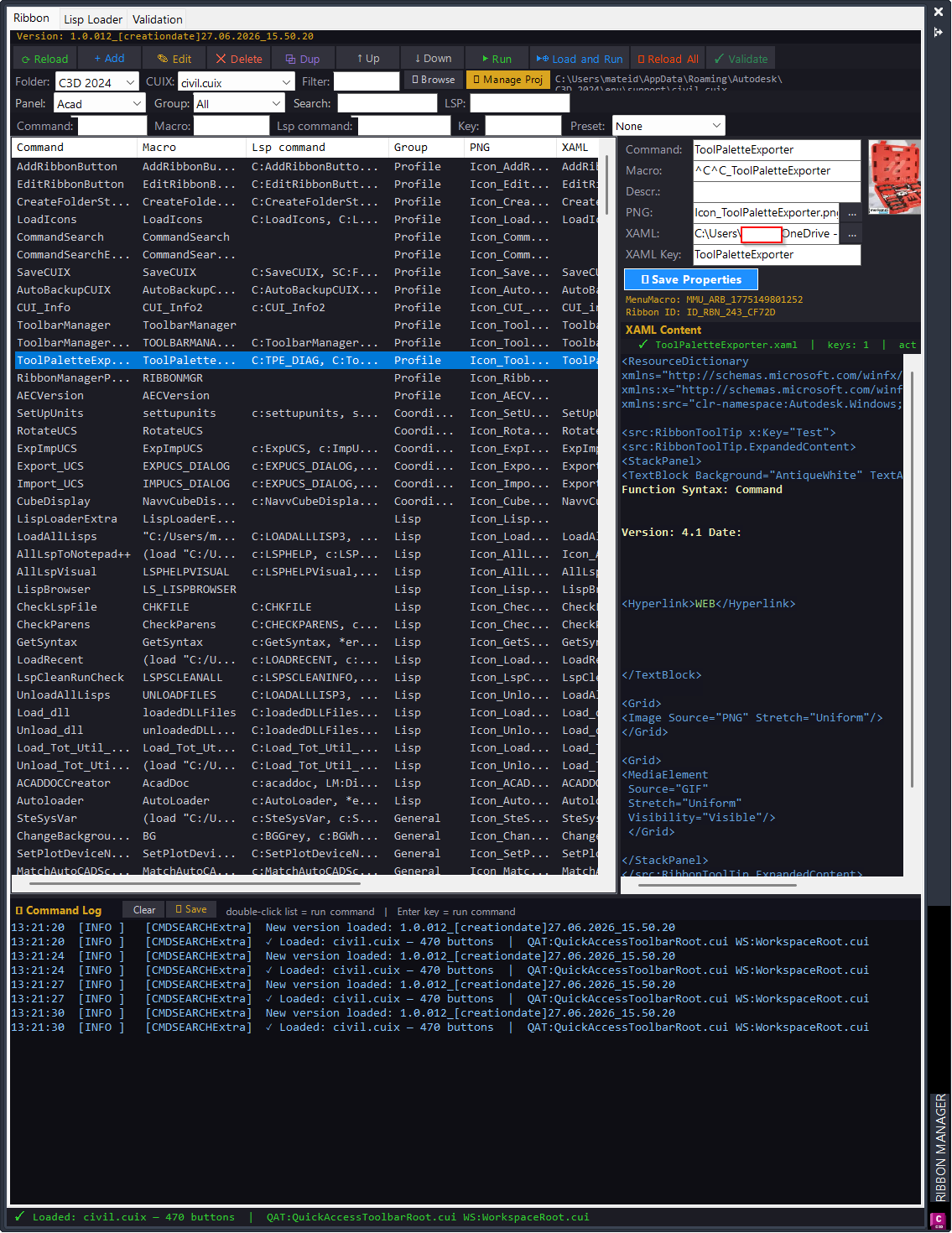
CommandSearchExtra
• Modeless AutoCAD command search palette opened with CMDSEARCHExtra.
• Ribbon CUIX command browsing with command, macro, group, PNG, XAML key, file size, created date, and modified date columns.
• Advanced filtering by command, macro, LSP command, group, source key, empty values, duplicate values, wildcard patterns, and preset filters.
• Direct command execution, load-and-run support, reload visible commands, and command row context actions.
• Ribbon button management for add, edit, delete, duplicate, move, save properties, browse image, browse XAML, and preview help content workflows.
• CUIX engine for reading Ribbon panels, groups, subgroups, buttons, menu macros, QAT data, workspaces, double click actions, and ZIP entries.
• Image path audit tools for finding missing Ribbon icons, checking existing paths, rebatching missing images, and setting common icon folders.
• Embedded Lisp Loader tab and standalone LISPLOADEXTRA window.
• AutoCAD and Civil 3D support folder scanning for LSP, VLX, FAS, and DLL files.
• Load checked, load selected, reload, report, export checked paths, live log, open folder, open file, copy path, and open-at-command-line workflows.
• FileSystemWatcher based automatic rescan when supported files are created, deleted, renamed, or modified.
• AutoLISP analysis that ignores comments and string literals while extracting command defuns, helper defuns, line numbers, and dependencies.
• Validation tab for duplicate command names, duplicate XAML keys, duplicate macro strings, missing macros, missing files, macro-to-defun mismatch, hard-coded path warnings, dependency checks, large-file warnings, and duplicate LSP commands.
• CSV and HTML export for validation results.
• HTML command catalog generation for Ribbon command documentation.
• Timestamped CUIX backup before saving changes.
• Layout persistence for filters, column widths, and repeated CAD management sessions.
• Diagnostic command LISPLOADDIAG for scanning loaded assemblies for LISP-related invocation methods.
• Core parser and filter self-test command CMDSEARCHExtraTESTS.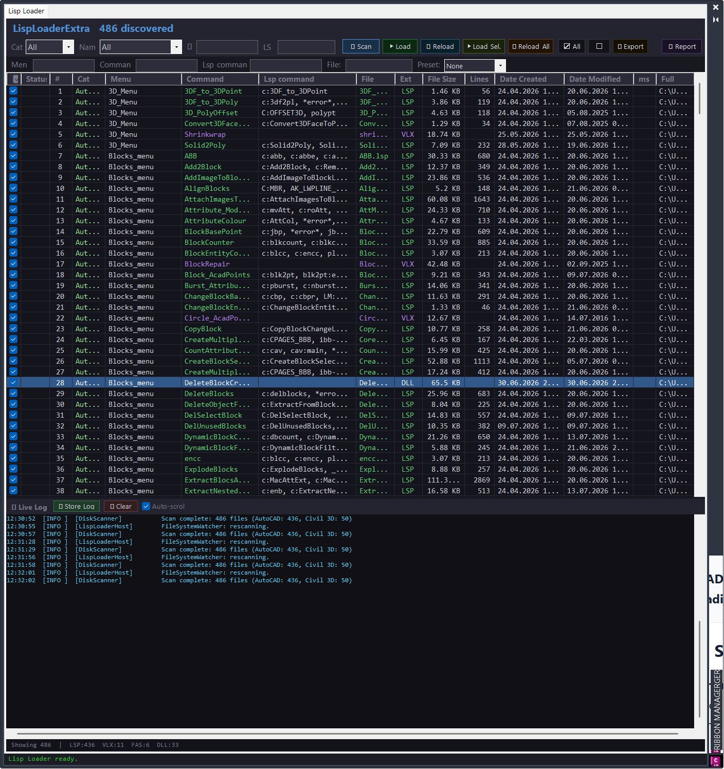
CommandSearch Lisp Loader Only
– Search ribbon commands from selected CUIX files.
– Filter by panel, group, command name, macro text, LSP command, XAML key, and missing or duplicate metadata.
– Add, edit, delete, duplicate, move, run, load and run, and reload ribbon command rows.
– Read CUIX data directly from ZIP-based CUIX XML files without Autodesk.AutoCAD.Customization.
– Work with [username]_ribbon_ panel naming conventions.
– Audit PNG image paths, XAML help files, XAML SourceKey values, duplicate command names, duplicate macro strings, and missing LSP command links.
– Scan structured Help_File folders for LSP, VLX, FAS, and DLL loader files.
– Extract AutoLISP C: defun command names and display them in loader columns.
– Load checked files, load selected rows, reload checked files, and reload all visible loader files.
– Use a batch loading path that enters AutoCAD application context once per reload session.
– Watch disk changes and rescan when support files are modified.
– Persist checked rows, filters, column widths, and layout state between sessions.
– Open file folders, open source files in an editor, copy paths, copy row data, and jump to LSP command lines.
– Record scan, load, warning, error, and diagnostic messages in a live log panel.
– Export loader paths, CSV or HTML validation reports, and command documentation.
– Run CMDSEARCHTESTS to verify core parser and filter logic.
– Run LISPLOADDIAG to inspect available LISP invocation methods in loaded assemblies.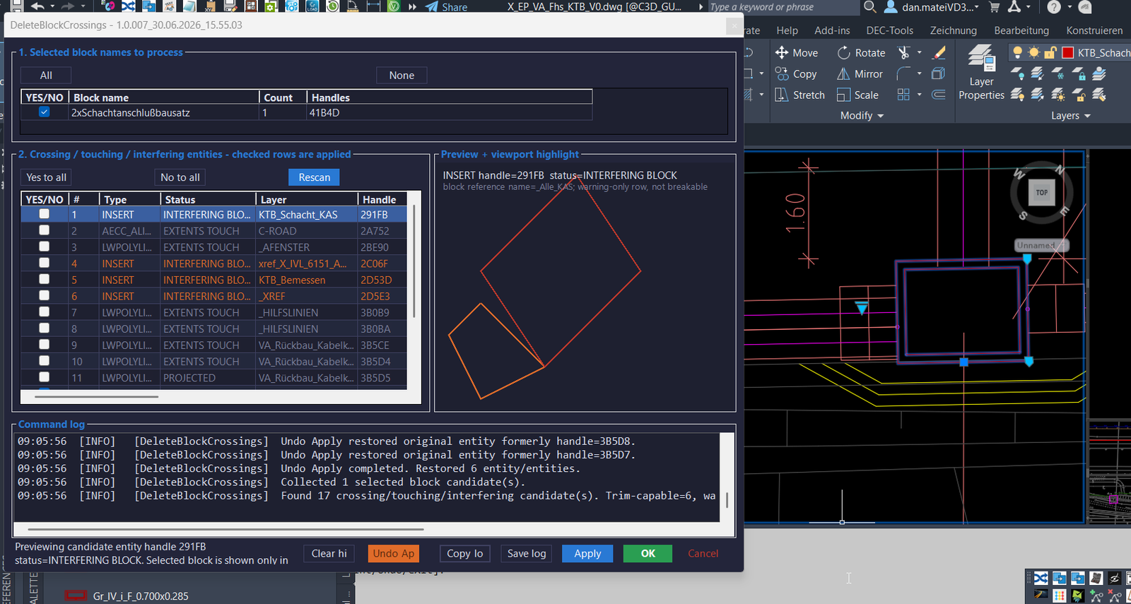
DeleteBlockCrossings
- 🚀 Launch crossing cleanup workflow – run
DELETEBLOCKCROSSINGS,DBC, orABBSto open a modeless AutoCAD Civil 3D cleanup tool. - 📌 Select block references – use pickfirst selection or a prompted
INSERTfilter to choose the block references that define the cleanup zones. - 🔢 Group selected blocks by name – display selected block names, counts, handles, and process toggles so repeated block references can be enabled or disabled together.
- 🔍 Scan crossing and touching geometry – find curves, block references, extents overlaps, projected crossings, tangent contacts, and warning-only interference candidates.
- 📐 Trim safe crossing curves – automatically trim checked
CROSSINGrows by removing the curve portion inside the selected block frame. - 🟧 Show warning-only diagnostics – keep
TOUCHING,CROSSING - CHECK,PROJECTED,EXTENTS TOUCH, andINTERFERING BLOCKrows visible for manual QA review. - 🎨 Preview candidate geometry – display sampled entity geometry and block frame context in the preview panel for faster visual confirmation.
- 🔍 Viewport highlight – highlight the active candidate in the AutoCAD drawing without leaving the modeless management workflow.
- 🔄 Rescan after changing block filters – update selected block processing state and rebuild the crossing candidate table.
- ✅ Check all and none controls – quickly enable or disable block groups and trim-capable crossing rows before applying changes.
- ↩️ Undo last apply – restore original entities and erase generated curve pieces from the last trim operation.
- 📝 Copy and save logs – copy the live log or save a diagnostic report with version, selected block handles, candidate handles, statuses, and intersection points.
- 🔒 Persist user choices – remember form size, form position, and enabled block-name settings in
DeleteBlockCrossings.cfg. - 🧰 Developer-friendly build output – use timestamped local build folders to reduce DLL lock problems while testing with AutoCAD
NETLOAD.
- 🚀 Launch crossing cleanup workflow – run
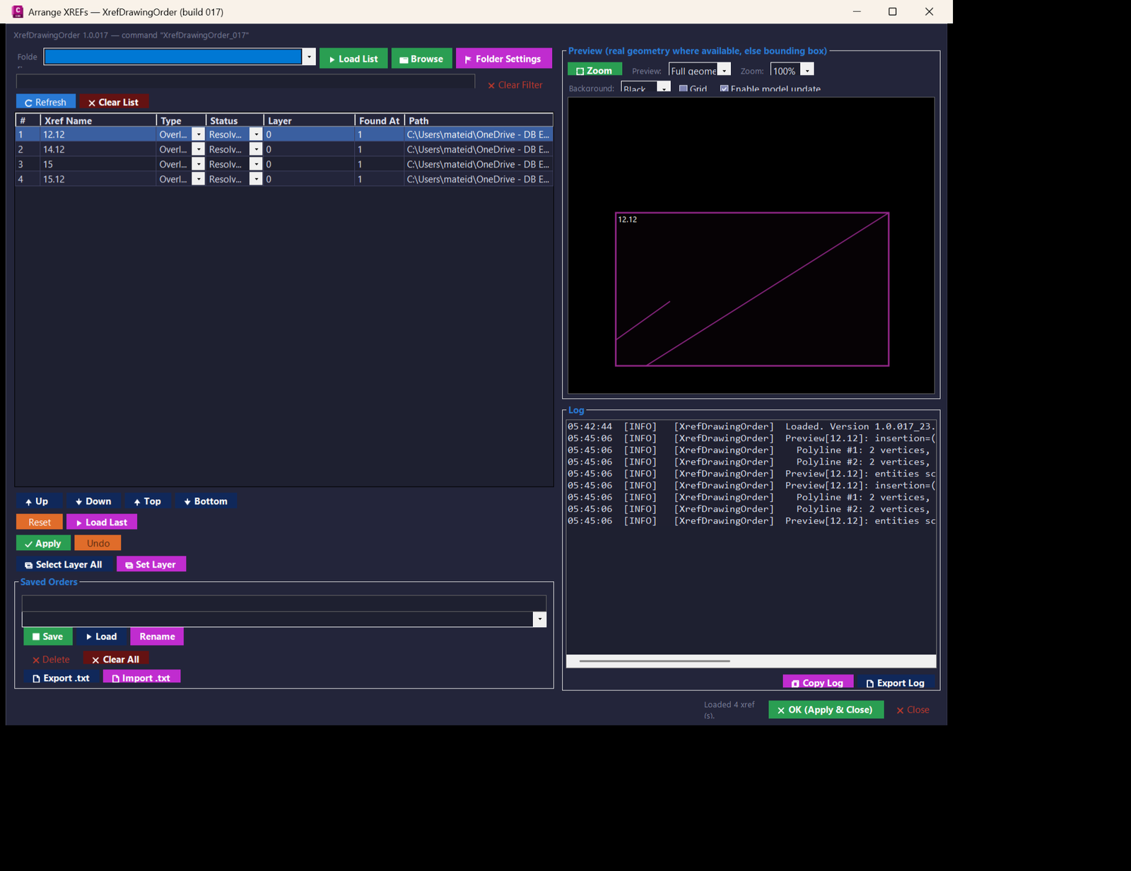
XrefsDrawingOrder
🔍 Search and filter xrefs — filters the grid by xref name so large drawings remain manageable.
📊 Full xref metadata grid — displays order number, xref name, attach or overlay type, load status, layer, instance count, and source path.
↕️ Reorder front-to-back stack — moves selected xrefs Up, Down, Top, Bottom, or by drag and drop while preserving multi-selection order.
🚀 Apply draw order — applies the arranged xref order back into AutoCAD using queued DRAWORDER operations.
↩️ One-level Undo — restores the previous applied xref order when the last Apply needs to be reversed.
💾 Save and load named orders — stores reusable xref stacking presets by name in the user profile.
📥 Import and export order TXT — shares xref order lists as plain text files for project standards, backups, and reuse.
🧠 Drawing-level last-order memory — stores the last used order in the drawing Named Objects Dictionary under XREFDRAWORDER_ORDERS.
🖼️ Live preview panel — shows xref extents and available real geometry for visual checking before applying changes.
🔎 Zoom to selected xref — focuses the AutoCAD viewport and the preview panel on the selected xref.
🟦 Preview modes — supports Fast preview using extents and Full geometry preview where linework extraction is available.
🧮 Preview diagnostics — logs insertion, rotation, scale, local coordinates, transformed coordinates, entity counts, and skipped entities for selected xrefs.
🧱 Xref status control — reloads, unloads, or detaches selected xrefs from the same interface.
🔗 Attach or overlay conversion — converts xref reference type when the selected reference needs a different dependency behavior.
🏷️ Set xref layer — updates the layer of one or more xref block references.
📁 Folder favorites — stores commonly used folders for import and export workflows.
📋 Copy names and paths — copies selected xref names or file paths to the clipboard.
📝 Persistent logs — displays live log output and supports copying or exporting diagnostic messages.
🖥️ Adaptive dialog sizing — opens at a screen-aware size for laptop and larger monitor workflows.
🎨 Civil 3D styled UI — uses a dark themed interface with consistent functional button colors and generated icons.LayerLeaderPlugin_test
✅ Modeless AutoCAD toolbar panel with the LLP and SHOWPANEL commands.
✅ PLACELEADER command for entity-based MLeader annotation using DB-standard display labels.
✅ Layer database manager based on layer_database.json with add, remove, list, refresh, apply, undo, and delete workflows.
✅ Dynamic block label manager based on block_database.json with wildcard matching for block names and visibility states.
✅ Place on Block workflow for dynamic blocks, including visibility-state label resolution such as matching X_2.80_2.30_* patterns.
✅ LLUPDATEFIELDS command to refresh source-object-backed MLeader label fields in the active drawing.
✅ Automatic DB MLeader style creation and activation on plugin load.
✅ Automatic BoQ.01_Text layer setup using ACI color 11 and Continuous linetype.
✅ Setup Styles integration through SETUPDIMSTYLES and LOADSETUPDIMSTYLES commands.
✅ Integrated SetupOverriteDimStyles.lsp and Background_Mask.lsp copied beside the DLL at build time.
✅ Native Setup Styles panel for Text, Dimensions, and MLeader style control.
✅ Background mask controls for text, dimensions, and multileaders.
✅ Arrowhead symbol support using AutoCAD standard MLeader arrowheads.
✅ UCS-aware position handling for placed leaders and block labels.
✅ Horizontal label rotation convention preserved after the v1.0.023 block-label correction.
✅ Log tab with timestamped activity, store log, clear log, copy log, and auto-persist options.
✅ Visual Studio 2022, .NET Framework 4.8, x64, Windows Forms, Newtonsoft.Json, and AutoCAD Civil 3D ObjectARX references.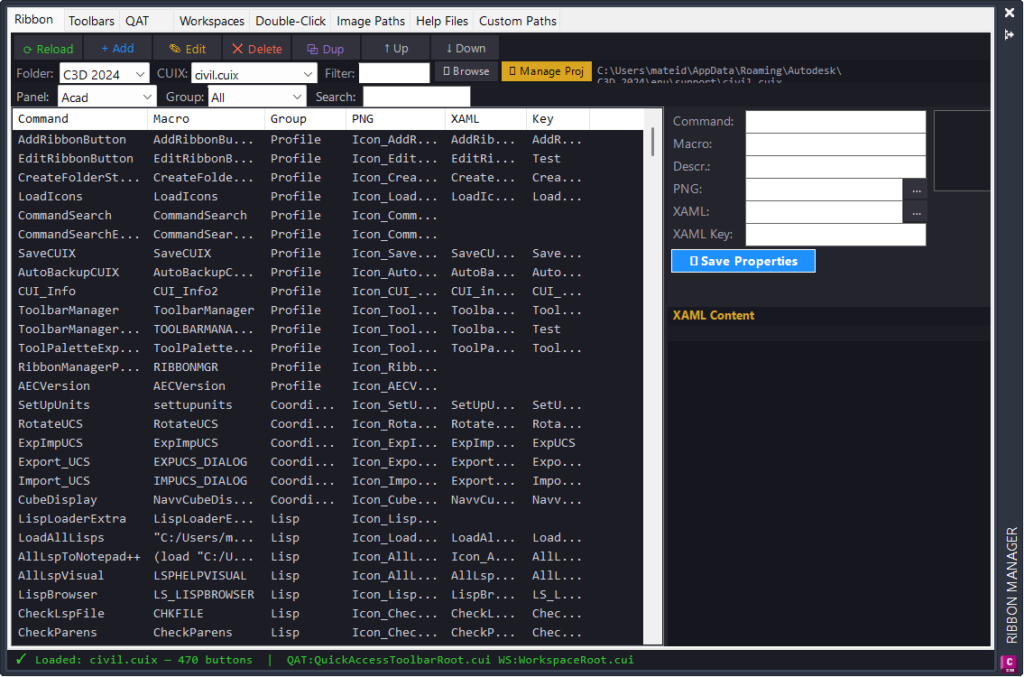
RibbonManagerPlugin
Open a dockable/snappable AutoCAD PaletteSet from the RIBBONMGR command.
Auto-detect common Civil 3D support folders and load available CUIX files, including civil.cuix.
Browse manually for any CUIX file and load its ribbon structure.
List [username]_ribbon_* panels, groups, sub-groups, command buttons, toggle buttons, macros, images, help files, and help keys.
Search and filter ribbon commands through the palette.
Add new ribbon buttons with command name, macro, button style, display name, description, tags, keytip, tooltip title, icon path, and XAML help reference.
Edit existing ribbon buttons while preserving lookup through OriginalCmd.
Duplicate selected ribbon buttons and create copy commands.
Delete ribbon buttons from the CUIX XML.
Move and reorder buttons inside the ribbon layout.
Save edited properties back to CUIX and reload AutoCAD menus.
Preview selected PNG icon paths and XAML help content.
Audit valid, missing, and empty image paths.
Repath missing images by matching Icon_Command.png or Command.png from a selected folder.
Batch-set Acad, C3D, or shared Icons-folder image paths.
Copy Icon_*.png files into the Civil 3D Icons folder when using the Icons workflow.
Display Quick Access Toolbar commands, standard items, and controls.
Display workspace information and workspace XML.
Display double-click actions from the CUIX.
Expose help file and custom path tabs for production setup checks.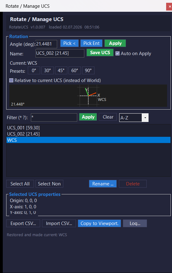
RotateUcs_vs.01
- 🚀 Open a modeless UCS manager —
ROTATEUCSandRUCSopen a floating WinForms palette for UCS rotation and named UCS management. - ⚡ Run quick no-dialog UCS rotation —
RU1rotates the UCS by a typed angle and immediately saves, restores, and aligns the view. - 📐 Run quick entity-based UCS rotation —
RUEextracts an entity angle, rotates the UCS, saves the UCS, restores it, and applies PLAN current behavior. - 🔢 Rotate UCS by typed angle — the palette applies a typed angle using AutoCAD managed matrix operations instead of command-line UCS calls.
- 📌 Use common angle presets — preset buttons quickly set common UCS rotation angles such as 0, 30, 45, 60, and 90 degrees.
- 📐 Pick angle from drawing —
Editor.GetAngleallows interactive angle selection, with an absolute-bearing correction when relative mode is off. - 🧩 Pick supported entity angle — the plugin extracts angles from lines, polylines, arcs, xlines, rays, and splines.
- 🔄 Rotate relative to current UCS — the user can choose whether the rotation is applied from WCS or relative to the current UCS.
- 💾 Save named UCS records — the current UCS can be saved into the AutoCAD UCS table through
UcsTableRecord. - 🏷️ Auto-generate UCS names — the plugin creates names such as
UCS_001 [45.00]using the next available sequence number. - 📚 Browse existing UCS records — the palette lists WCS and drawing-defined UCS records.
- 🔍 Filter UCS names with wildcards — users can filter the UCS list with
*and?. - 📊 Sort UCS records — the list can be sorted A-Z, Z-A, by length, or with the current UCS first.
- 🔎 Restore by double-click — double-clicking a list item restores the selected UCS and aligns the view.
- 📝 Show UCS properties — the palette displays origin, X-axis, and Y-axis values for the selected UCS.
- 🎯 Highlight selected UCS in the viewport — a transient X and Y axis marker is drawn for the selected UCS row.
- 📘 Preview UCS rotation live — the custom preview panel shows the rotated UCS axes while the angle changes.
- ✏️ Rename selected UCS — one selected named UCS can be renamed from the palette.
- 🧹 Delete selected UCS records — selected named UCS records can be deleted while WCS is protected.
- 📤 Export UCS definitions to CSV — names, origins, and axis vectors can be exported for backup or transfer.
- 📥 Import UCS definitions from CSV — saved UCS definitions can be recreated or overwritten from CSV data.
- 🪟 Copy UCS to paper-space viewport — a selected UCS can be applied to a selected layout viewport using per-viewport UCS settings.
- 📋 View and save logs — the detached log window records session messages and supports manual log saving.
- 💾 Remember user settings — angle, name, filter, relative mode, auto-save state, sort mode, and dialog location persist between sessions.
- 🔴 Important limitation — this plugin manages AutoCAD UCS records and viewport UCS behavior only. It does not directly edit Civil 3D objects such as
ProfileView,SectionView,Alignment, surfaces, labels, bands, corridors, or pipe networks. - 🔴 CSV limitation — CSV import uses simple comma splitting and should be tested carefully with unusual UCS names or complex CSV values.
- 🔴 Build path limitation — the project imports a machine-specific ObjectARX reference props file and may require reference path edits on another workstation.
- 🔐 Platform limitation — this is a Windows AutoCAD and Civil 3D .NET plugin, not an AutoLISP-only workflow.
- 🚀 Open a modeless UCS manager —
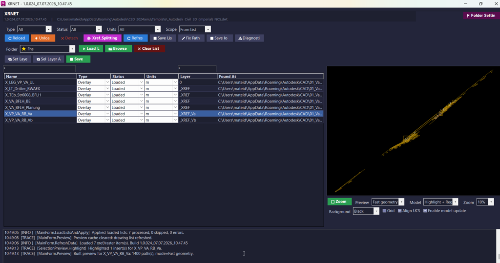
UnReloadDetachSelectedXrefs_vs.02
- 🚀 Open XRNET xref manager – run
XRNETto open a modeless xref control panel inside AutoCAD or Civil 3D. - 🔍 Scan active DWG references – lists DWG xrefs and raster images with name, type, status, units, layer, and resolved path.
- 🔄 Reload selected references – refreshes selected xrefs and raster images so the drawing uses updated external files.
- 🟧 Unload selected references – unloads xrefs or hides raster images while keeping the reference structure available.
- 🔴 Detach selected references – removes unwanted DWG xrefs or raster images from the active drawing.
- 📌 Attach missing list entries – applies saved xref list entries and attaches missing DWG files at origin.
- 🧩 Convert xref type – changes references between
OverlayandAttachedwhere the code can preserve placement. - 🧹 Set organized xref layers – moves references onto clean layers such as generated
xref_namelayers. - 📊 Load and save xref lists – reads and writes TXT reference lists for repeatable project workflows.
- 📤 Export CSV reports – exports selected xref splitter rows for review, documentation, or coordination.
- 🧠 Fix and validate paths – detects missing paths, blank paths, and path problems, then supports folder-based repair workflows.
- 📐 Preview selected references – displays selected DWG geometry or raster-related preview data before applying changes.
- 🔢 Zoom, pan, fit, grid, and UCS options – improves visual inspection with practical CAD-style preview controls.
- 📝 Edit xref splitter rows – adds, deletes, reorders, validates, edits, and applies xref list entries.
- 🏷️ Generate layers and abbreviations – creates practical layer names and short names for organized xref split lists.
- 📘 Manage predefined folders – stores project folder shortcuts for faster file selection and relative path workflows.
- 🔒 Use dry-run mode – checks apply actions before modifying the active drawing.
- 🧰 Save logs and diagnostics – exports operation logs and diagnostic information for troubleshooting.
- 🎨 Use reliable WinForms icons – displays generated bitmap button icons instead of unsupported color emoji text rendering.
- 🚀 Open XRNET xref manager – run
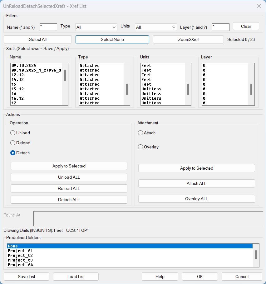
UnReloadDetachSelectedXrefs_01
Functionalities- Filter xrefs by Name wildcard, Type, Units, and Layer wildcard, then work only on the visible subset.
- Select All and Select None for the currently filtered list, with a live selected counter.
- Zoom2Xref zooms to the Model Space extents of the first selected xref insert set.
- Operations on selected using the Operation radio group and Apply to Selected: Unload, Reload, Detach.
- Operations on all using dedicated buttons: Unload ALL, Reload ALL, Detach ALL.
- Attachment type conversion using the Attachment radio group and Apply to Selected: Attach or Overlay.
- Attachment conversion on all using dedicated buttons: Attach ALL, Overlay ALL.
- Save List writes a text file containing only the selected xrefs with their key properties (Name, Type, Found At, UnitsCode, Layer) plus host metadata (INSUNITS and UCSNAME).
- Load List reads a saved list, attaches missing xrefs from Found At paths, enforces stored units during attach, reloads them, and restores host settings after completion.
- Predefined folders allow Save List and Load List dialogs to open directly in the selected project folder: None, Project_01, Project_02, Project_03, Project_04, Project_05.
Text2Multileader_01
Functionalities- Creates one MLEADER from multiple text entities.
- Automatically orders the note content using insertion point Y coordinates to preserve reading order in typical stacked notes.
- Supports leader point extraction from LINE start and end points.
- Supports leader point extraction from LWPOLYLINE or POLYLINE by using the first and last vertex coordinates.
- Sets the leader text width using the maximum bounding-box width among selected text objects for more consistent wrapping behavior.
- Performs cleanup by deleting the source leader geometry and deleting the original text objects after successful creation.
- Prints warnings when the chosen polyline has insufficient points or when the selected leader object is not supported.
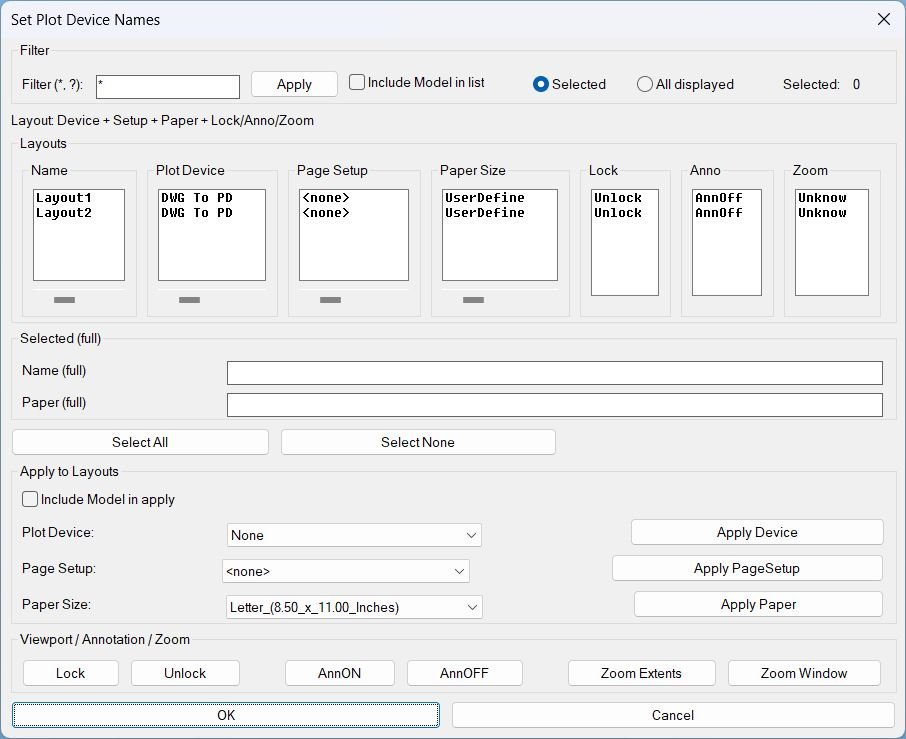
SetPublishLocation_01
Functionalities- Apply Device sets the plot device for targeted layouts and refreshes plot device info.
- Apply PageSetup copies a selected page setup into targeted layouts, or clears it when none is chosen.
- Apply Paper sets the canonical media name based on the selected device and selected paper display name.
- Lock locks all applicable paper-space viewports for targeted layouts.
- Unlock unlocks all applicable paper-space viewports for targeted layouts.
- AnnON turns ANNOALLVISIBLE on for targeted paper-space layouts.
- AnnOFF turns ANNOALLVISIBLE off for targeted paper-space layouts.
- Zoom Extents zooms extents inside each viewport for targeted layouts and marks those layouts to display ZExt in the Zoom column.
- Zoom Window prompts for two corners inside a viewport on the first targeted layout, then applies the same window zoom across targeted layouts without marking ZExt.
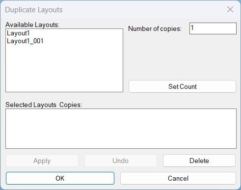
DuplicateLayouts_01
Functionalities- Queue layouts for duplication
- Select an available layout and set Number of copies.
- Press Set Count to add or update the queued entry in the summary list.
- Displays queued items as layout : count for review before applying.
- Batch duplicate layouts
- Apply duplicates all queued layouts and keeps the dialog open for additional changes.
- OK duplicates all queued layouts then exits, and exits silently if nothing is queued.
- Each duplicate is created with a unique name BaseName_### to prevent naming conflicts.
- Delete behavior
- If a summary row is selected, Delete removes that queued entry only and does not change the drawing.
- If no summary row is selected and an available layout is selected, Delete deletes that layout tab from the drawing and switches CTAB to Model first if the tab was active.
- Deletion blocks invalid targets such as Model and missing layouts with clear alerts.
- Undo within the session
- Undo runs a single step undo using UNDO 1 for the last duplication batch or delete operation executed in this dialog session.
- The tool enables the Undo button only after at least one operation was performed during the session.
- UI rules
- Apply is disabled until at least one layout is queued with Set Count.
- OK remains enabled always, and will only duplicate when there are queued items.
- Queue layouts for duplication
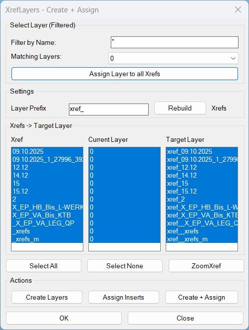
CreatesXrefsLayersAssign_01
Dialog Controls and Actions- Filter by Name Filters the Matching Layers dropdown (non-Xref layers only).
- Assign Layer to all Xrefs Moves all XREF inserts in the drawing to the selected Matching Layer and sets it current.
- Layer Prefix Controls how Target Layer names are generated (Prefix + XrefName).
- Rebuild Re-scans XREFs and refreshes all lists and the layer filter results.
- Xref List shows detected XREF names and supports multi-select.
- Current Layer List shows where each XREF insert currently resides: single layer name, <varies>, or <none>.
- Target Layer List previews the computed target layer per XREF using the current prefix.
- Select All Selects every XREF row in all three columns.
- ZoomXref Zooms to the first selected XREF inserts extents in Model Space without closing the dialog.
- Select None Clears selection in all three columns.
- Create Layers Creates missing per-XREF target layers (color 7) for the selected XREFs (or all if none selected).
- Assign Inserts Moves selected XREF inserts onto their computed target layers (Prefix + XrefName) with locked-layer safety.
- Create + Assign Runs Create Layers then Assign Inserts in one step for the selected XREFs (or all if none selected).
- OK Closes the dialog only.
- Close Closes the dialog only.
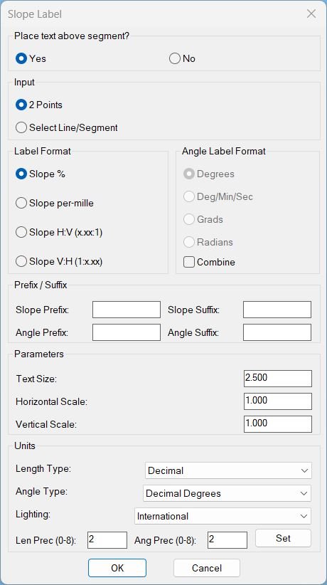
Slope_01
Key functionalities of slope_p: • Dual input modes: 2-point mode or entity-selection mode, switchable in the dialog. • Flexible slope formats: Percentage, per-mille, H:V ratio (x.xx:1), or V:H ratio (1:x.xx). • Optional angle label: Can show angle in Degrees, DMS, Grads, or Radians; may be combined on a second line under the slope. • Prefix / Suffix control: Independent prefix/suffix strings for slope and angle text (e.g., “S=” or “α=” etc.). • Scaling & offset: User-set text height, horizontal/vertical scale factors (to respect vertical exaggeration), and above/below toggle for label offset from the line. • Drawing units integration: Dialog can read and set LUNITS, AUNITS, LIGHTINGUNITS, and their precisions for consistent numeric formatting. • Segment-wise labeling: For polylines, every segment is processed individually with its own midpoint and orientation. • Robust checks: Skips zero-length segments, handles vertical slopes (INF) and guards against invalid numeric inputs.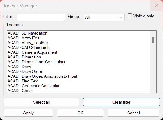
ToolbarManager
• Centralized toolbar overview: Lists all toolbars across all menu groups in one dialog, showing their group and name so you can understand your full toolbar set at a glance. • Text filtering: Allows you to type a partial name or wildcard into the filter box to narrow the list to toolbars whose labels match that pattern, making it easy to find related toolbars. • Group based view: Lets you restrict the view to a single menu group or to All, so you can manage toolbars for a specific add on or workspace separately. • Visible only mode: When enabled, shows only toolbars that are currently visible in the UI, useful for cleaning up or saving an existing configuration. • Multi selection control: Supports multiple selection in the list box so you can toggle on a whole set of toolbars at once while hiding the rest in the current view. • Select all helper: The Select all button selects every toolbar in the current view in one click, ready to be applied as a visible set. • Incremental apply: The Apply button updates toolbar visibility without closing the dialog so you can interactively refine your setup, adjusting the filter, group, or selections as you go. • Persistent view settings: Remembers the last used filter text, visible only condition, and selected group in global variables, making subsequent uses of ToolbarManager feel continuous within the session.Slope_00
• Slope formatting options — Percent, integer ratios, or decimal ratios • Scale-aware slope calculation — Applies H/V multipliers before evaluating run & rise • Negative slope detection — Prepends “-” when dy indicates descending elevation • Robust ratio reduction — Converts values like 200:100 into 2:1 cleanly • Special case protections — Vertical/horizontal slopes produce INF-safe labels • Controlled text placement — Aligns TEXT with segment and offsets above/below automatically • System variable safety — Temporarily sets and restores OSMODE and LUPREC • Dialog-driven settings — Radio buttons ensure mutually exclusive format choicesCloseParalelPolylines
• Entity filtering Skips unsupported types and informs the user • Count enforcement Ensures exactly two valid entities; warns if fewer or more • Automatic opening of polylines Closed LWPOLYLINE is forced open with a status message • Endpoint connection Creates LINE from start-to-start and end-to-end via ENTMAKEX • Automatic joining Uses PEDIT multiple and join to merge all entities into one polyline • Failure handling Gracefully aborts with a message if selection invalid or empty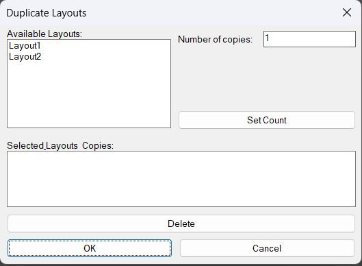
DuplicateLayouts_00
- • Runtime DCL generation creates and deletes a temporary dialog file automatically.
- • Layout list shows available paper-space layouts and excludes Model from duplication choices.
- • Per-layout copy counts lets the user assign different copy quantities per selected layout using the Set Count workflow.
- • Summary management displays the configured list of layouts and counts and allows removal via Delete prior to running copies.
- • Automated naming generates new layout names by appending a two-digit sequence suffix to the source layout name.
- • Command-based duplication performs duplication using ._layout _copy for each requested copy instance.
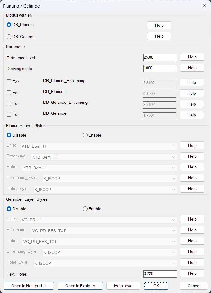
DB_Planung_Gelände
• Two main modes: Supports separate Planum and Gelaende workflows that share the same configuration dialog but use different layers, styles, and offsets for drawn labels. • Persistent configuration: Saves and reloads mode, reference level, scale, offsets, layers, styles, and edit flags so that each drawing remembers its last annotation settings automatically. • Interactive geometry picking: Asks the user to pick the intersection between center line and band, then finds cartridge and profile reference lines and repeatedly prompts for quotation points along the profile to place labels. • Automatic layer creation: Ensures all required Planum and Gelaende layers exist before drawing, and temporarily uses auxiliary layers for highlighting while restoring their colors after finishing. • Leader and label generation: For each picked quotation point it creates a vertical leader line from the point to the band, and places one distance text and one elevation text at configurable offsets below the band on their dedicated layers and styles. • Scale aware values: Converts drawing distances to real world distances using the configured drawing scale, and adds the reference elevation to the vertical difference to compute absolute heights. • Style enable options: Allows disabling or enabling layer and style dropdowns for Planum and Gelaende groups, which can lock them to configuration values or let the user freely choose from layer and style lists. • Context sensitive help: Multiple Help buttons open image files or a sample DWG showing what each parameter, layer, style, or mode represents, assisting the user in configuring complex settings. • Undo friendly: When undo is enabled, wraps the geometry operations into an undo group so the created labels and temporary changes can be reverted in a single step if needed.
CubeDisplay_Off_On
Main Functionalities: • Turns off and re-enables the Navigation Cube display automatically. • Uses vla-sendcommand instead of manual user input, allowing programmatic control from scripts or macros. • Provides a quick way to refresh the ViewCube when it becomes unresponsive or missing. • Compatible with AutoCAD 2010+ versions supporting NAVVCUBEDISPLAY command.