
Short description
Sort / Purpose: Create a new polyline segment copied between two picked points on an existing LWPOLYLINE, place it on a chosen layer, and optionally extend, rotate, move, and generate multiple offset copies via an interactive dialog with Apply and Undo.
• Scope: Works only on a selected LWPOLYLINE, extracting the portion between two points along the polyline and building a new, separate polyline from that segment.
• Goal: Speed up creation of repeated pipe or band segments with controlled layer assignment, geometric extension at ends, rotation, perpendicular distance, and multiple parallel offsets using presets.
Command:
Command name: CopySelection
How to run: Load the LISP file, then type CopySelection in the command line and press Enter.
• Entity selection: First select one LWPOLYLINE when prompted “Select LWPolyline”; other entity types are rejected.
• Point selection: Specify the first and second points on that polyline; the routine projects those picks onto the polyline and uses the segment between them as the base for the new geometry.
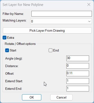
• Dialog control: A dialog named PLDupeLayerEx is shown where you choose the target layer, filter layers by name, enable or disable Extra options, and use Apply, Undo, OK, or Cancel to control the operation.
Description:
• Polyline and points: After you choose an LWPOLYLINE, the routine asks for two points along it, snaps them to the closest points on the curve, and ensures they are not identical before continuing.
• Segment extraction: Uses curve parameters at the two picked locations to slice the source polyline between those parameters, reconstructing a new vertex list that represents only the chosen segment (including bulges and widths).
• Header cloning: Copies the original polyline’s non vertex DXF data, forces the new polyline onto the chosen target layer, and clears the closed flag so the result is an open segment.
• Layer dialog: Builds a temporary DCL file that provides a text filter for layer names, a popup list of matching layers, a button to pick a layer from an existing object, and a toggle to enable or disable Extra transform options.
• Layer filtering and pick: Collects all non xref layers, sorts them, filters them dynamically as you type in the filter box, and lets you optionally pick an entity in the drawing to adopt its layer as the target.
• Extra options group: When Extra is enabled, the dialog exposes rotation start or end toggle, rotation angle, perpendicular distance, offset style presets, numeric offset, offset copy count, and numeric extension at start and end.
• Extension at ends: The extend-ends helper extends the first and last segments of the new polyline by independent distances extS and extE along their segment directions, updating coordinates through COM.
• Rotation and distance: Computes a unit direction from the first pick to the second, then rotates the new polyline around the chosen base point (start or end) by the given angle, and moves it perpendicular to that direction by the specified distance.
• Offset copies: Creates additional parallel copies of the transformed polyline, spaced by the offset distance along the normal direction, up to the specified offset count; the offset value can be auto filled from presets like DN110, KK I to KK IV.
• Persistent settings: Stores the last used layer and filter string in environment variables so that the next run of the command remembers which layer and filter you used previously.
• Apply and Undo loop: Wraps operations in a global UNDO group, marks the undo stack before each Apply, and supports stepping back one Apply at a time when you press Undo, without closing the dialog.
• Finalization logic: If you never used Apply or Undo, pressing OK performs a single geometry creation using current dialog values; if you cancel, all Apply actions in this session are undone before closing the group.
Helper function: (if any)
Geometry helpers:
• tan: Simple tangent function used when computing bulge values for polyline vertex reconstruction.
• LM:LWVertices: Extracts vertices of a lightweight polyline into a structured list containing position, start width, end width, and bulge for each vertex, used by the PLDUPE style segment slicing logic.
• extend-ends: Uses VLA coordinates to extend the first and last segments of the new LWPOLYLINE by extS and extE along their unit direction vectors, handling both two vertex and multi vertex polylines.
Segment creation core:
• CS:MakeGeometry: Main builder that slices the original LWPOLYLINE between two curve parameters, builds a new open polyline on the chosen layer, then applies optional extension, rotation, distance move, and offset copy generation when Extra is enabled.
Dialog and state helpers:
• get-all-layers: Iterates over the drawing’s layer table via COM, collects all non xref layers into a sorted list for the layer popup.
• update-layer-list: Filters the layer list by the current filter string, rebuilds the popup content, and selects either the picked layer, last used layer, or the first match as current choice.
• set-extra-mode: Enables or disables all Extra related tiles (rotation, distance, offsets, extension values) depending on the Extra toggle, greying them out when Extra is off.
• CS:read-values: Reads all current dialog fields (filter, layer, Extra flag, rotation choice, angle, distance, offset, offset count, and extension values), converts them to numbers, clamps offset count to non negative integers, and updates environment variables for filter and layer.
• Offset presets: The offset type popup selects among DN110 and KK variants, and an action tile maps each choice to a predefined numeric offset value written back into the offset edit box.
Undo session control:
• applyCount and flags: Tracks how many times Apply has been used, whether there is any applied geometry present, and whether the user has interacted with Apply or Undo, to decide how OK and Cancel should behave regarding undoing or keeping changes.
Functionalities:
• Segment duplication: Quickly duplicates only a chosen portion of an LWPOLYLINE between two points, instead of copying and trimming manually.
• Layer targeting: Lets you send the new polyline and its copies directly onto a specific layer chosen from a filtered list or from a picked object, keeping layer structure organized.
• Optional advanced transforms: When Extra is on, you can extend ends, rotate the new polyline around the start or end point, shift it perpendicular to its own direction, and generate several parallel copies at fixed offset distances.
• Preset offset library: Built in presets (DN110, KK I to KK IV) automatically set offset distances that match typical pipe or trench sizes, saving you from repeatedly typing standard values.
• Interactive Apply and Undo: You can iteratively test different settings: Apply to create geometry, Undo to remove the last created batch, adjust dialog values, and repeat, all on the same source polyline selection.
• Robust cancellation: If you close the dialog or choose Cancel after one or more Apply actions, the routine automatically undoes all those actions so the drawing returns to its original state.
• Single step final undo: When you finish with OK, all geometry created in this session remains, but the entire operation is enclosed in an UNDO group so one undo command removes everything if needed.
Result:
Result: A new polyline segment is created from the selected portion of the original LWPOLYLINE, placed on the chosen layer, and optionally extended, rotated, shifted, and replicated as multiple offset copies according to your dialog settings.
• Efficient profile building: Complex pipe or band arrangements along an alignment can be generated from a single base polyline, with each functional run duplicated and positioned with precise numeric control rather than manual edits.
• Consistent offsets and angles: Repeated elements share the same extension, rotation, distance, and offset parameters, giving your layout a uniform and standards compliant appearance.
• Safe experimentation: Apply and Undo inside the dialog let you experiment with different combinations of offsets, angles, and extension distances, knowing that Cancel can revert everything and OK will keep the final configuration in a single undo block.
• Workflow memory: The command remembers your last layer and filter, so subsequent runs in the same project feel streamlined with minimal repetitive input.
Copy code:
Images, animations etc.
Log in to download.
Log in
Log in
XAML code:
<ResourceDictionary
xmlns="http://schemas.microsoft.com/winfx/2006/xaml/presentation"
xmlns:x="http://schemas.microsoft.com/winfx/2006/xaml"
xmlns:src="clr-namespace:Autodesk.Windows;assembly=AdWindows">

<src:RibbonToolTip x:Key="CopySelection">
<src:RibbonToolTip.ExpandedContent>
<StackPanel>
<TextBlock Background="AntiqueWhite" TextAlignment="Left">
<Bold>Function Syntax: CopySelection</Bold>
<LineBreak/>
<Bold>Version: 1 Date: 01.11.2025</Bold>
<LineBreak/>
<LineBreak/>
<Hyperlink>AI + https://www.theswamp.org/index.php?topic=59415.0</Hyperlink>
<LineBreak/>
<Bold>Purpose</Bold><LineBreak/>
This program duplicates a selected segment of an LWPolyline between two user picked points, and creates the new polyline on a user selected layer chosen from a dialog with live name filtering or by picking a layer from an object in the drawing.<LineBreak/>
<LineBreak/>

<Bold>Primary Command</Bold><LineBreak/>
<Span Foreground="DarkRed"><Bold>CopySelection</Bold></Span> prompts for one LWPolyline, two points on it, then creates a new LWPolyline segment copy on a chosen layer.<LineBreak/>
<LineBreak/>

<Bold>User Workflow</Bold><LineBreak/>
1. Run <Span Foreground="DarkRed"><Bold>CopySelection</Bold></Span> in the AutoCAD command line.<LineBreak/>
2. Select one <Span Foreground="DarkRed"><Bold>LWPOLYLINE</Bold></Span> entity when prompted.<LineBreak/>
3. Specify the first point, then specify the second point, both of which are snapped to the closest points on the selected polyline.<LineBreak/>
4. A layer picker dialog opens, where the user can filter layers by name, select a layer from a dropdown list, or pick a layer from an existing object in the drawing.<LineBreak/>
5. If the user confirms a layer selection, the program duplicates only the polyline segment between the two points and creates a new polyline on the chosen layer.<LineBreak/>
<LineBreak/>

<Bold>Key Inputs and Validation</Bold><LineBreak/>
<ul><LineBreak/>
  <li><Bold>Polyline selection</Bold> The command requires selecting an entity and verifies it is of type <Span Foreground="DarkRed"><Bold>LWPOLYLINE</Bold></Span>.<LineBreak/></li><LineBreak/>
  <li><Bold>Two distinct points</Bold> The user must pick two different points, the routine re projects each pick to the closest point on the polyline using <Span Foreground="DarkRed"><Bold>vlax-curve-getclosestpointto</Bold></Span>, and it rejects identical points with a distinct points required message.<LineBreak/></li><LineBreak/>
  <li><Bold>Layer selection</Bold> The user must choose a valid layer in the dialog, otherwise the operation is cancelled without creating a new polyline.<LineBreak/></li><LineBreak/>
</ul><LineBreak/>
<LineBreak/>

<Bold>Layer Picker Dialog</Bold><LineBreak/>
The command dynamically writes a temporary DCL file and opens a dialog titled <Span Foreground="DarkRed"><Bold>Set Layer for New Polyline</Bold></Span>.<LineBreak/>
It supports filtering and a pick from drawing workflow.<LineBreak/>
<LineBreak/>

<Bold>Layer Filtering Behavior</Bold><LineBreak/>
<ul><LineBreak/>
  <li>The dialog has an edit box labeled <Span Foreground="DarkRed"><Bold>Filter by Name</Bold></Span> that filters the layer list to matching entries.<LineBreak/></li><LineBreak/>
  <li>The filter uses wildcard matching logic by surrounding the typed text with * so it behaves like contains match, and it uses case insensitive comparison by converting names to uppercase.<LineBreak/></li><LineBreak/>
  <li>The list of available layers excludes Xref dependent layers by skipping names that match the pattern containing a pipe character, which are typically Xref layer names.<LineBreak/></li><LineBreak/>
  <li>The dialog remembers the last used layer and last used filter using environment variables so subsequent runs start from the previous context.<LineBreak/></li><LineBreak/>
</ul><LineBreak/>
<LineBreak/>

<Bold>Pick Layer From Drawing</Bold><LineBreak/>
The dialog includes a button <Span Foreground="DarkRed"><Bold>Pick Layer From Drawing</Bold></Span> that closes the dialog temporarily, prompts the user to select an object, reads that object layer, and then re opens the dialog with that layer pre selected if it exists in the layer list.<LineBreak/>
<LineBreak/>

<Bold>Persistent Settings</Bold><LineBreak/>
The command stores and retrieves user preferences using environment variables.<LineBreak/>
<ul><LineBreak/>
  <li><Span Foreground="DarkRed"><Bold>PLDUPE_LastLayer</Bold></Span> stores the last chosen layer name, initially set to the original layer of the selected polyline as the default baseline.<LineBreak/></li><LineBreak/>
  <li><Span Foreground="DarkRed"><Bold>PLDUPE_LastFilter</Bold></Span> stores the last typed filter text for the layer dialog.<LineBreak/></li><LineBreak/>
</ul><LineBreak/>
<LineBreak/>

<Bold>Polyline Segment Duplication Logic</Bold><LineBreak/>
After layer confirmation, the routine duplicates only the portion of the polyline between the snapped points p and q, using curve parameters and vertex reconstruction logic derived from PLDUPE style behavior.<LineBreak/>
<LineBreak/>

<Bold>How the Segment Range is Determined</Bold><LineBreak/>
<ul><LineBreak/>
  <li>It computes curve parameters m and n at points p and q using <Span Foreground="DarkRed"><Bold>vlax-curve-getparamatpoint</Bold></Span>.<LineBreak/></li><LineBreak/>
  <li>If the parameters are reversed, it swaps m and n and also swaps p and q so the segment is processed in forward order along the polyline.<LineBreak/></li><LineBreak/>
  <li>It extracts LWPolyline vertex data using <Span Foreground="DarkRed"><Bold>LM:LWVertices</Bold></Span>, capturing each vertex point and width and bulge data for reconstruction.<LineBreak/></li><LineBreak/>
</ul><LineBreak/>
<LineBreak/>

<Bold>Bulge and Width Handling</Bold><LineBreak/>
<ul><LineBreak/>
  <li>The routine includes a tangent helper <Span Foreground="DarkRed"><Bold>tan</Bold></Span> and uses it to adjust bulge values when trimming at fractional parameters.<LineBreak/></li><LineBreak/>
  <li>If the start point p lies within a segment rather than exactly at a vertex, it inserts a new synthetic vertex at p with interpolated start width and adjusted bulge for the partial segment.<LineBreak/></li><LineBreak/>
  <li>If the end point q lies within a segment rather than exactly at a vertex, it inserts a new synthetic vertex at q and adjusts widths and bulge accordingly to end the duplicated segment cleanly.<LineBreak/></li><LineBreak/>
</ul><LineBreak/>
<LineBreak/>

<Bold>New Polyline Creation</Bold><LineBreak/>
The new polyline is created using <Span Foreground="DarkRed"><Bold>entmakex</Bold></Span>, reusing most of the original polyline entity data but substituting specific fields for the new entity.<LineBreak/>
<ul><LineBreak/>
  <li><Bold>Layer</Bold> The entity data is updated so group 8 is set to the user selected layer name.<LineBreak/></li><LineBreak/>
  <li><Bold>Closed flag</Bold> The closed bit is removed from group 70 so the new segment is not forced closed.<LineBreak/></li><LineBreak/>
  <li><Bold>Extrusion and normal</Bold> The routine preserves the polyline normal vector using group 210 from the original entity data to keep the new polyline oriented correctly in 3D context.<LineBreak/></li><LineBreak/>
  <li><Bold>Elevation and header data</Bold> It preserves elevation and header fields from the original LWPolyline by carrying forward group 39 and associated header data where applicable.<LineBreak/></li><LineBreak/>
</ul><LineBreak/>
<LineBreak/>

<Bold>Temporary File Cleanup</Bold><LineBreak/>
The command writes the dialog definition to a temporary DCL file and deletes it after the dialog workflow completes using <Span Foreground="DarkRed"><Bold>vl-file-delete</Bold></Span>.<LineBreak/>
<LineBreak/>

<Bold>Important Commands and Aspects</Bold><LineBreak/>
<Span Foreground="DarkRed"><Bold>CopySelection</Bold></Span> main command entry point.<LineBreak/>
<Span Foreground="DarkRed"><Bold>entsel</Bold></Span> used to select the LWPolyline and to pick an object for layer extraction.<LineBreak/>
<Span Foreground="DarkRed"><Bold>getpoint</Bold></Span> used to specify the two points, then projected to the polyline.<LineBreak/>
<Span Foreground="DarkRed"><Bold>vlax-curve-getclosestpointto</Bold></Span> snaps picked points onto the polyline accurately.<LineBreak/>
<Span Foreground="DarkRed"><Bold>PLDUPE_LastLayer</Bold></Span> remembers last selected layer across runs.<LineBreak/>
<Span Foreground="DarkRed"><Bold>PLDUPE_LastFilter</Bold></Span> remembers last filter text across runs.<LineBreak/>
<Span Foreground="DarkRed"><Bold>Pick Layer From Drawing</Bold></Span> lets the user derive a layer choice from an existing object.<LineBreak/>
<Span Foreground="DarkRed"><Bold>entmakex</Bold></Span> creates the new polyline representing the duplicated segment.<LineBreak/>
<LineBreak/>

<Bold>Messages and Edge Cases</Bold><LineBreak/>
<ul><LineBreak/>
  <li>If no entity is selected at the start, it prints a no entity selected message and exits with no changes.<LineBreak/></li><LineBreak/>
  <li>If the selected object is not an LWPolyline, it prints a not an LWPolyline message and exits with no changes.<LineBreak/></li><LineBreak/>
  <li>If the two picked points resolve to the same closest point on the polyline, it forces the user to pick a distinct second point.<LineBreak/></li><LineBreak/>
  <li>If the user cancels the dialog or does not confirm a layer, it prints a no layer selected operation cancelled message and does not create a new polyline.<LineBreak/></li><LineBreak/>
  <li>If the user picks a layer from an object that is not present in the layer list, it reports that the picked layer was not found and does not apply it as the selection.<LineBreak/></li><LineBreak/>
</ul><LineBreak/>
<LineBreak/>

<Bold>Operational Summary</Bold><LineBreak/>
This program will require the user to select an <Span Foreground="DarkRed"><Bold>LWPOLYLINE</Bold></Span>, then specify two distinct points which are projected onto that polyline, then choose a target layer using a dialog with name filtering or by picking a layer from an object, after which the program reconstructs and duplicates only the polyline segment between the two points including widths and bulges, creates a new polyline via <Span Foreground="DarkRed"><Bold>entmakex</Bold></Span> on the selected layer, preserves the original normal orientation, and cleans up the temporary dialog file while remembering the last used layer and filter for the next run.<LineBreak/>


</TextBlock>

<Grid>
<Image Source="PNG" Stretch="Uniform"/>
</Grid>

<Grid>
<MediaElement
Source="Rec 0010.gif"
Stretch="Uniform"
Visibility="Visible"/>
</Grid>

</StackPanel>
</src:RibbonToolTip.ExpandedContent>
</src:RibbonToolTip>
</ResourceDictionary>
Additional info:
Based on / Source code:
Open Website
Share this page:
Subscribe
Login
0 Comments
Oldest
Tags: 🏷️ Autocad Lisps, 🏷️ Polyline menu
Tags: 🏷️ Autocad Lisps, 🏷️ Polyline menu