
Short description
Comming soon …
Command:
Comming soon …
Description:
Comming soon …
Helper function: (if any)
Comming soon …
Functionalities:
Comming soon …
Result:
Comming soon …
Images, animations etc.
XAML code:
<ResourceDictionary
xmlns="http://schemas.microsoft.com/winfx/2006/xaml/presentation"
xmlns:x="http://schemas.microsoft.com/winfx/2006/xaml"
xmlns:src="clr-namespace:Autodesk.Windows;assembly=AdWindows">

<src:RibbonToolTip x:Key="30Degree">
<src:RibbonToolTip.ExpandedContent>
<StackPanel>
<TextBlock Background="AntiqueWhite" TextAlignment="Left">
<Bold>Function Syntax: 30deg</Bold>
<LineBreak/>
<Bold>Version: 1.0 Date: 26.06.2026 18:18:42</Bold>
<LineBreak/>
<Bold>Version: 1.1 Date: 27.06.2026 07:00:22</Bold>
<LineBreak/>
<Bold>Version: 1.2 Date: 27.06.2026 07:49:46</Bold>
<LineBreak/>
<Bold>Version: 1.3 Date: 27.06.2026 7:48:32AM</Bold>
<LineBreak/>
<Hyperlink>Ai+https://www.lee-mac.com/dynamicoffset.html</Hyperlink>

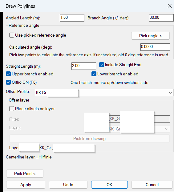
<Bold>Description</Bold> <LineBreak/> <Run>This AutoLISP command creates an interactive AutoCAD tool named </Run><Run Foreground="DarkRed" FontWeight="Bold">30deg</Run><Run>. The program opens a DCL dialog where the user defines angled branch geometry, offset profile size, branch behavior, Ortho mode behavior, optional picked reference angle, and target offset layer settings.</Run> <LineBreak/> <Run>The tool requires the user to </Run><Run Foreground="DarkRed" FontWeight="Bold">pick a base point</Run><Run> in the drawing. From that point, it dynamically previews and draws one active angled branch at a time, normally used for cable tray or similar profile routing.</Run> <LineBreak/> <Run>The branch direction can be evaluated from the default reference direction or from a user-picked reference angle. When a picked reference angle is used, the user selects two points in the drawing and the command calculates the reference angle from those points.</Run> <LineBreak/> <Run>The mouse position controls the active side and branch direction relative to the active reference angle: moving the mouse to the right or left of the base point controls the routing side, while moving the mouse above or below the base point activates the corresponding upper or lower branch.</Run> <LineBreak/> <Run>The constructed centerline is automatically placed on the layer </Run><Run Foreground="Magenta" FontWeight="Bold">_Hilflinie</Run><Run>, while the offset/profile edge lines can be placed on a selected target layer from the dialog.</Run> <LineBreak/>
<Bold>Functionalities</Bold> <LineBreak/> <Run> Opens a custom </Run><Run Foreground="DarkBlue" FontWeight="Bold">DCL dialog</Run><Run> for configuring the polyline generation before placement.</Run> <LineBreak/> <Run> Allows the user to define the </Run><Run Foreground="DarkRed" FontWeight="Bold">angled branch length</Run><Run> in meters.</Run> <LineBreak/> <Run> Allows the user to define the </Run><Run Foreground="DarkRed" FontWeight="Bold">branch angle</Run><Run>, with a default value of 30 degrees.</Run> <LineBreak/> <Run> Provides a </Run><Run Foreground="DarkBlue" FontWeight="Bold">Reference angle</Run><Run> section where the user can optionally calculate the active reference angle by picking two points in the drawing.</Run> <LineBreak/> <Run> Includes a </Run><Run Foreground="DarkBlue" FontWeight="Bold">Pick angle <</Run><Run> button that temporarily returns to the drawing and asks the user to select two points used for angle calculation.</Run> <LineBreak/> <Run> Displays the calculated reference angle in a dedicated </Run><Run Foreground="DarkGreen" FontWeight="Bold">Calculated angle</Run><Run> field in degrees.</Run> <LineBreak/> <Run> Includes a </Run><Run Foreground="DarkRed" FontWeight="Bold">Use picked reference angle</Run><Run> checkbox. When enabled, the calculated angle becomes the active reference direction for the branch logic.</Run> <LineBreak/> <Run> If no reference angle is picked, or if </Run><Run Foreground="DarkRed" FontWeight="Bold">Use picked reference angle</Run><Run> is not enabled, the command uses the old behavior with a reference angle of 0 degrees.</Run> <LineBreak/> <Run> Provides two branch option checkboxes for enabling the </Run><Run Foreground="DarkRed" FontWeight="Bold">upper branch</Run><Run> and the </Run><Run Foreground="DarkRed" FontWeight="Bold">lower branch</Run><Run>.</Run> <LineBreak/> <Run> Both branch options are enabled by default, but the command previews and creates only </Run><Run Foreground="DarkRed" FontWeight="Bold">one active branch</Run><Run> at a time, based on the mouse position relative to the picked base point and active reference angle.</Run> <LineBreak/> <Run> Includes an optional </Run><Run Foreground="DarkGreen" FontWeight="Bold">straight end segment</Run><Run> after the angled branch.</Run> <LineBreak/> <Run> Allows the user to define the length of the straight end segment independently from the angled branch length, with a typical default value of </Run><Run Foreground="DarkGreen" FontWeight="Bold">2.00 m</Run><Run>.</Run> <LineBreak/> <Run> The straight end segment is drawn parallel to the active reference direction, using the forward direction for the right side and the opposite direction for the left side.</Run> <LineBreak/> <Run> Provides an </Run><Run Foreground="DarkGreen" FontWeight="Bold">Ortho ON</Run><Run> checkbox in the dialog, checked by default, so the command can keep AutoCAD </Run><Run Foreground="DarkGreen" FontWeight="Bold">ORTHOMODE / F8</Run><Run> active during placement.</Run> <LineBreak/> <Run> The command does not force Ortho mode off after placement.</Run> <LineBreak/> <Run> Provides a profile selection list containing predefined </Run><Run Foreground="DarkBlue" FontWeight="Bold">KK cable channel profiles</Run><Run>.</Run> <LineBreak/> <Run> Each profile stores left and right offset distances used to generate the visible offset/profile edge lines.</Run> <LineBreak/> <Run> Dynamically previews the centerline and offset edge lines while the mouse moves.</Run> <LineBreak/> <Run> The dynamic length is controlled by the distance between the picked base point and the current mouse position.</Run> <LineBreak/> <Run> Pressing </Run><Run Foreground="Red" FontWeight="Bold">ESC</Run><Run> during placement cancels only the current placement and returns the user to the dialog without closing the command.</Run> <LineBreak/> <Run> Pressing the left mouse button commits the preview geometry into the drawing.</Run> <LineBreak/> <Run> Uses AutoCAD undo marks so each committed geometry action can be undone cleanly.</Run> <LineBreak/> <Run> Provides an </Run><Run Foreground="DarkBlue" FontWeight="Bold">Undo</Run><Run> button in the dialog to undo the last generated geometry.</Run> <LineBreak/>
<Bold>Reference Angle Area</Bold> <LineBreak/> <Run> Includes a dedicated </Run><Run Foreground="DarkBlue" FontWeight="Bold">Reference angle</Run><Run> section in the DCL dialog.</Run> <LineBreak/> <Run> The </Run><Run Foreground="DarkRed" FontWeight="Bold">Use picked reference angle</Run><Run> checkbox controls whether the picked and calculated angle is used by the branch creation logic.</Run> <LineBreak/> <Run> The </Run><Run Foreground="DarkBlue" FontWeight="Bold">Pick angle <</Run><Run> button asks the user to pick two points in the drawing.</Run> <LineBreak/> <Run> The command calculates the angle from the first picked point to the second picked point.</Run> <LineBreak/> <Run> The calculated value is shown in the </Run><Run Foreground="DarkGreen" FontWeight="Bold">Calculated angle</Run><Run> field.</Run> <LineBreak/> <Run> When the picked reference angle is active, mouse left/right and mouse up/down are evaluated relative to that calculated angle instead of world 0 degrees.</Run> <LineBreak/> <Run> When the picked reference angle is not active, the command keeps the previous behavior and uses 0 degrees as the reference direction.</Run> <LineBreak/>
<Bold>Offset Layer Area</Bold> <LineBreak/> <Run> Includes a dedicated </Run><Run Foreground="DarkBlue" FontWeight="Bold">Offset layer</Run><Run> section in the DCL dialog.</Run> <LineBreak/> <Run> The checkbox </Run><Run Foreground="DarkRed" FontWeight="Bold">Place offsets on layer</Run><Run> controls whether the offset/profile edge lines are moved to a selected layer.</Run> <LineBreak/> <Run> Includes a </Run><Run Foreground="DarkGreen" FontWeight="Bold">Filter</Run><Run> field for filtering the available drawing layers.</Run> <LineBreak/> <Run> Includes a </Run><Run Foreground="DarkGreen" FontWeight="Bold">Layer</Run><Run> dropdown showing the filtered layer results.</Run> <LineBreak/> <Run> Includes a </Run><Run Foreground="DarkBlue" FontWeight="Bold">Pick from drawing</Run><Run> button that allows the user to select an existing object and read its layer.</Run> <LineBreak/> <Run> Displays the currently selected offset layer name below the layer controls.</Run> <LineBreak/> <Run> If the selected offset layer does not exist, the program creates it automatically before placing the offset lines.</Run> <LineBreak/>
<Bold>Layer Logic</Bold> <LineBreak/> <Run> The </Run><Run Foreground="Magenta" FontWeight="Bold">centerline</Run><Run> created from the picked point is always placed on </Run><Run Foreground="Magenta" FontWeight="Bold">_Hilflinie</Run><Run>.</Run> <LineBreak/> <Run> If </Run><Run Foreground="Magenta" FontWeight="Bold">_Hilflinie</Run><Run> does not exist, the program creates it automatically.</Run> <LineBreak/> <Run> The centerline layer is set to </Run><Run Foreground="Magenta" FontWeight="Bold">magenta</Run><Run> and uses the </Run><Run Foreground="DarkGreen" FontWeight="Bold">Continuous</Run><Run> linetype.</Run> <LineBreak/> <Run> The offset/profile edge lines are placed on the selected offset layer when the offset layer option is active.</Run> <LineBreak/> <Run> If the offset layer option is disabled, the offset/profile edge lines remain on the current active drawing layer.</Run> <LineBreak/> <Run> Any offset layer matching </Run><Run Foreground="DarkBlue" FontWeight="Bold">VA_KTB_KK*</Run><Run> is set to AutoCAD color </Run><Run Foreground="DarkBlue" FontWeight="Bold">11</Run><Run>, not white.</Run> <LineBreak/>
<Bold>Profiles Used</Bold> <LineBreak/> <Run> </Run><Run Foreground="DarkBlue" FontWeight="Bold">KK Gr. I i.F_220X275</Run><Run> with 0.1100 m left offset and 0.1100 m right offset.</Run> <LineBreak/> <Run> </Run><Run Foreground="DarkBlue" FontWeight="Bold">KK Gr. II i.F_400X275</Run><Run> with 0.2000 m left offset and 0.2000 m right offset.</Run> <LineBreak/> <Run> </Run><Run Foreground="DarkBlue" FontWeight="Bold">KK Gr. IIIa i.F_515X275</Run><Run> with 0.2575 m left offset and 0.2575 m right offset.</Run> <LineBreak/> <Run> </Run><Run Foreground="DarkBlue" FontWeight="Bold">KK Gr. IV i.F_700X285</Run><Run> with 0.3500 m left offset and 0.3500 m right offset.</Run> <LineBreak/>
<Bold>Typical Workflow</Bold> <LineBreak/> <Run> The user runs the command </Run><Run Foreground="DarkRed" FontWeight="Bold">30deg</Run><Run>.</Run> <LineBreak/> <Run> Optional: the user clicks </Run><Run Foreground="DarkBlue" FontWeight="Bold">Pick angle <</Run><Run> and selects two points in the drawing to calculate a reference angle.</Run> <LineBreak/> <Run> Optional: the user enables </Run><Run Foreground="DarkRed" FontWeight="Bold">Use picked reference angle</Run><Run> so the calculated angle controls the branch reference direction.</Run> <LineBreak/> <Run> The user selects the branch length, branch angle, straight end option, straight end length, Ortho option, KK profile, and offset layer settings in the dialog.</Run> <LineBreak/> <Run> The user clicks </Run><Run Foreground="DarkBlue" FontWeight="Bold">Pick Point</Run><Run> or </Run><Run Foreground="DarkBlue" FontWeight="Bold">Apply</Run><Run>.</Run> <LineBreak/> <Run> The user selects a base point in the drawing.</Run> <LineBreak/> <Run> The tool dynamically previews one active centerline branch and its profile offset edges while the mouse moves.</Run> <LineBreak/> <Run> The user moves the mouse above or below the base point to choose the active upper or lower branch, and left or right to choose the side relative to the active reference angle.</Run> <LineBreak/> <Run> The user clicks to create the final polylines.</Run> <LineBreak/> <Run> The dialog returns after placement, allowing repeated use without restarting the command.</Run> <LineBreak/>
</TextBlock>

<Grid>
<Image Source="Image_000.png" Stretch="Uniform"/>
</Grid>

</StackPanel>
</src:RibbonToolTip.ExpandedContent>
</src:RibbonToolTip>
</ResourceDictionary>
Additional info:
Based on / Source code:
https://www.lee-mac.com/dynamicoffset.html